Text Solution
Verified by Experts


Topper's Solved these Questions
ELECTROMAGNETIC INDUCTION
CENGAGE PHYSICS ENGLISH|Exercise Solved Example|5 VideosELECTROMAGNETIC INDUCTION
CENGAGE PHYSICS ENGLISH|Exercise Exercise 3.1|15 VideosELECTRICAL MEASURING INSTRUMENTS
CENGAGE PHYSICS ENGLISH|Exercise M.C.Q|2 VideosELECTRON,PHONTS,PHOTOELECTRIC EFFECT & X-RAYS
CENGAGE PHYSICS ENGLISH|Exercise dpp 3.3|15 Videos
Similar Questions
Explore conceptually related problems
CENGAGE PHYSICS ENGLISH-ELECTROMAGNETIC INDUCTION-compression type
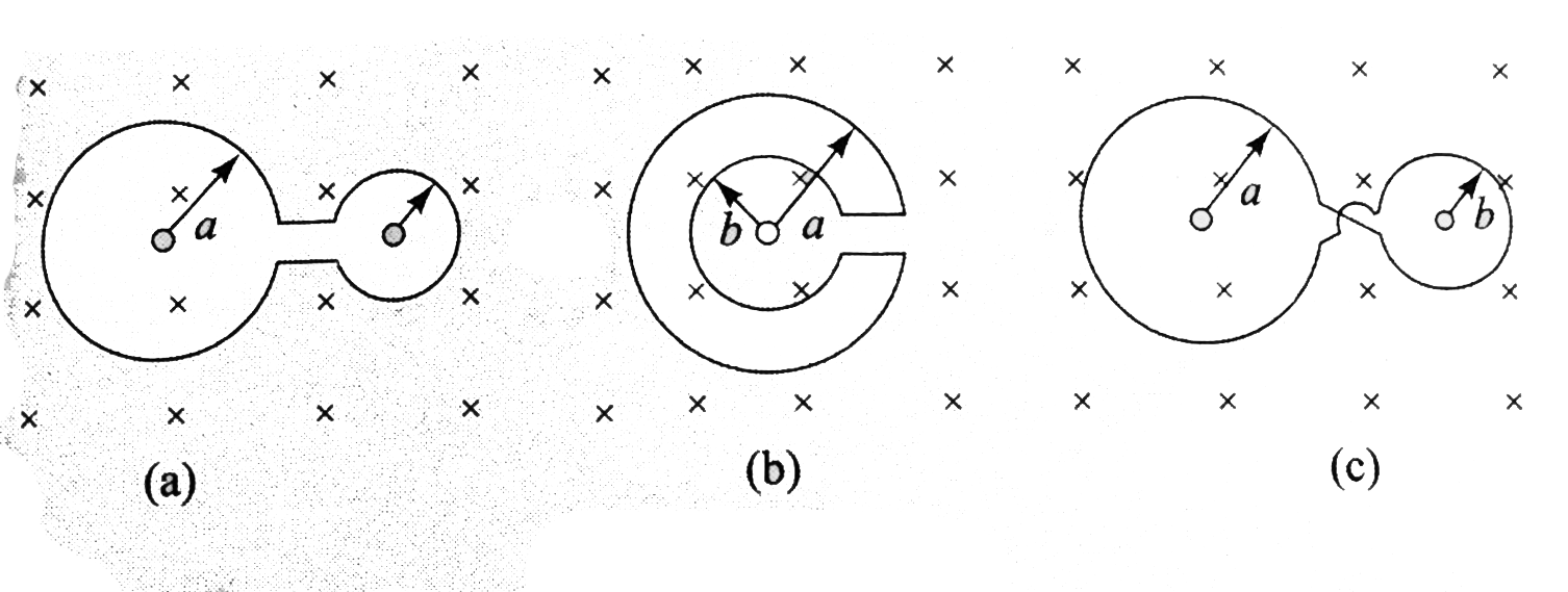
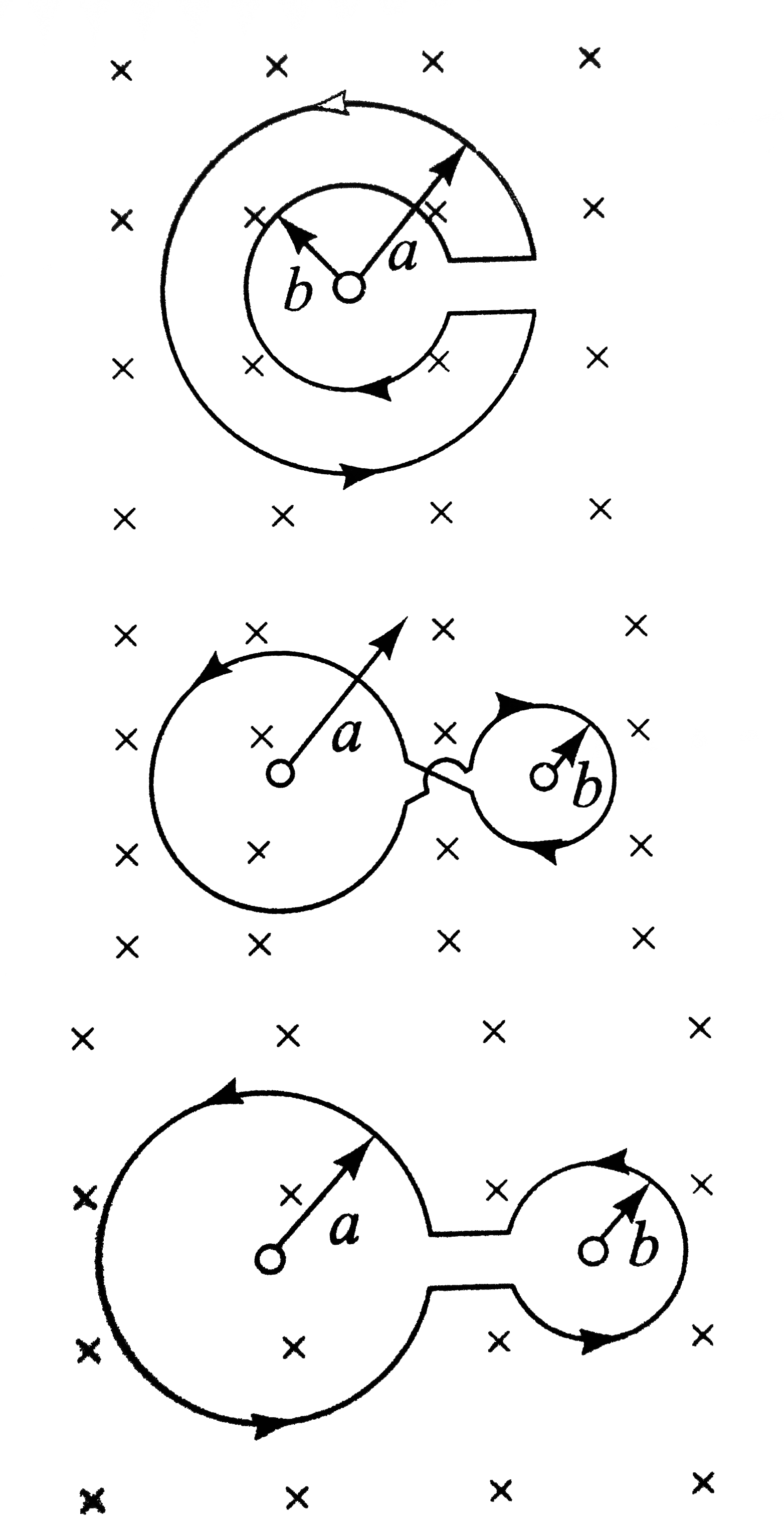
- Figure 3.15(a) shown two circular rings of radii a and b (a gt b) join...
Text Solution
|
- A thin non conducting ring of mass m, radius a carrying a charge q can...
Text Solution
|
- A thin non conducting ring of mass m, radius a carrying a charge q can...
Text Solution
|
- A thin non conducting ring of mass m, radius a carrying a charge q can...
Text Solution
|
- A thin non conducting ring of mass m, radius a carrying a charge q can...
Text Solution
|
- Light of wavelength 12000A is incident on a thin glass plate of refrac...
Text Solution
|
- In youngs double slit experiment the fringes are formed at a distance ...
Text Solution
|
- Laser light of wavelength 315 nm incident on a pair of slits produces ...
Text Solution
|