Home
Class 12
PHYSICS
A circuit containing a two position swit...

A circuit containing a two position switch `S` is shown in figure

a. The switch `S` is in position 1. Find the potential differecne `V_A-V_B` and the rte of production of joule heat in `R_1`
b. If now the switch `S` is put in position 2 at `t=0`. Find ltbRrgt i steady current in `R_4` and ii hte time when current in `R_4` is half the steady value. Also calculate the energy stored in the inductor `L` at that time.

Text Solution

Verified by Experts

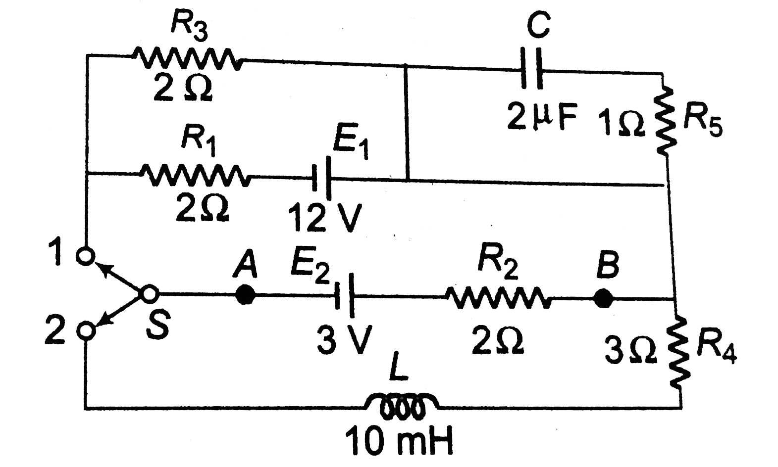
a. The capacitor offers infinite resistance to dc in the steady state, therefore, the current in capacitor branch is zero. The equivalent circuit, in steady state, when switch is in position (1) is given in Fig.
The distribution of current according to kirchhoff's first law is shows in Fig. Applying kirchhoff's second law to mesh abcda,

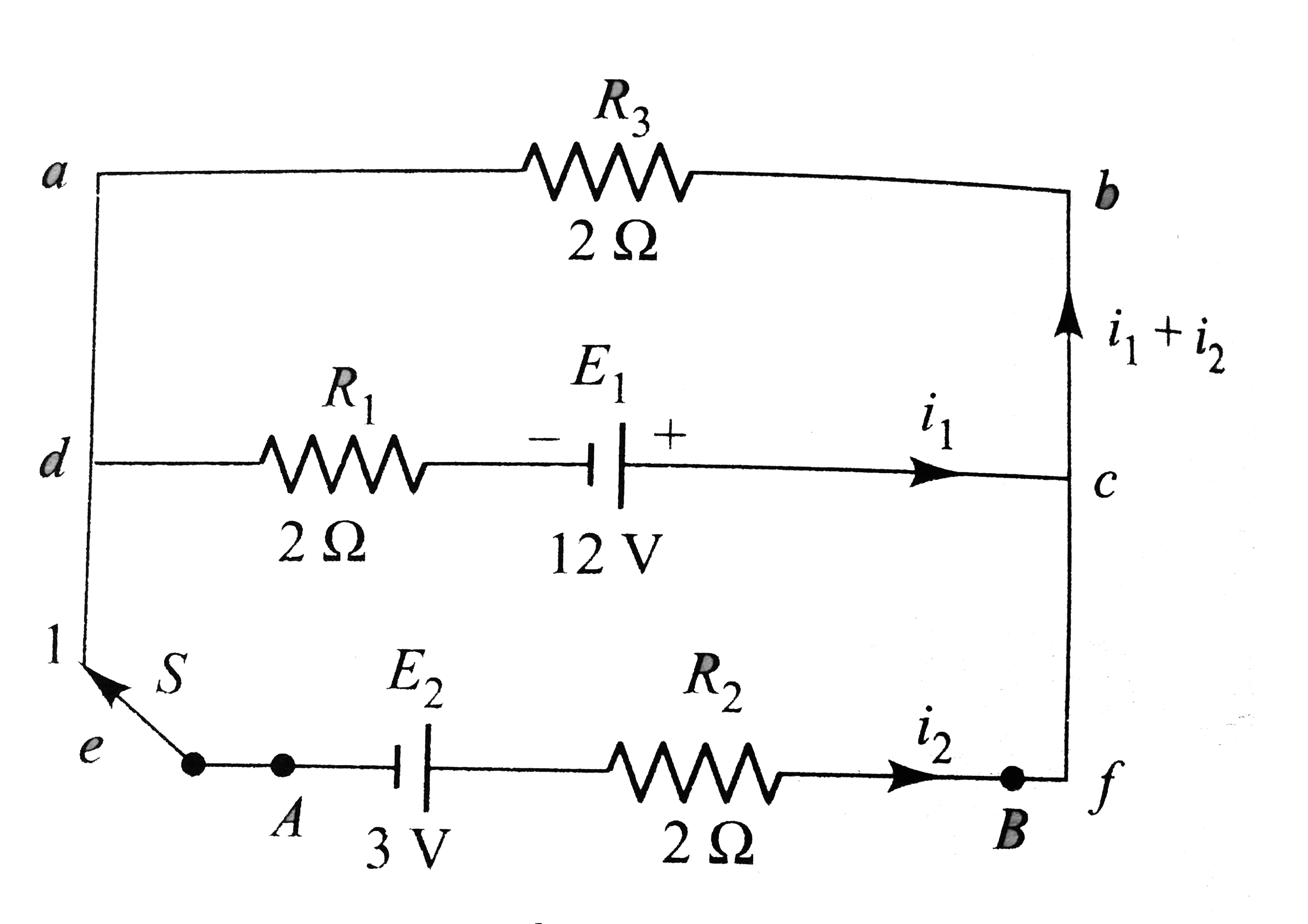
`i_(1) xx 2 + (i_(1) + i_(2)) xx 2 = 12`
or `4i_(1) + 2i_(2) = 12` or `2i_(1) + i_(2) = 6` (i)
Applying kirchhoff's second law to mesh abfea,
`i_(2) xx 2 + (i_(1) + i_(2)) 2 = 3` or `2i_(1) + 4i_(2) = 3` (ii)
Solving Eqs (i) and (ii), we get `i_(1) = 3.5 A, i_(2) =- 1A`
`:.` Potential difference between `A` and `B` is
`V_(B) - V_(A) = V = E_(2) - i_(2)R_(2) = 3 - (- 1) xx 2 = 5 V`
`:. V_(A) - V_(B) = - 5V`
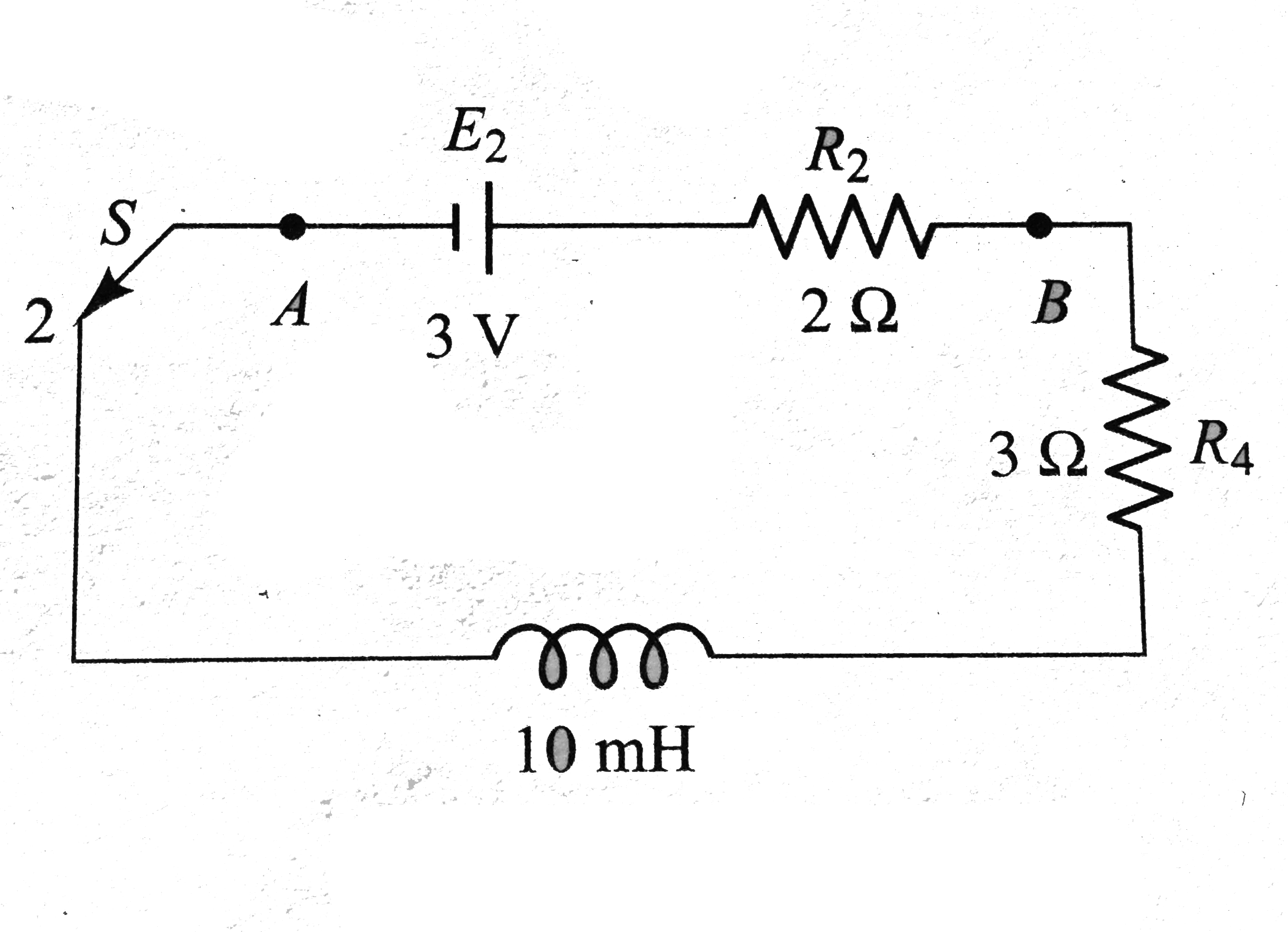
b. When switch `S` is put in position 2, the equivalent circuit takes the form as shows in Fig.
Total resistance of the circuit,
`R = R_(2) + R_(4) = 2 + 3 = 5 Omega`
`L = 10 mH = 10 xx 10^(-3) H`
In steady state, there is not role of inductor `L`.
`:.` Steady current
`i_(0) = (E)/(R) = (3)/(5) = 0.6 A`

The growth of current in `RL` circuit is given by
`i = i_(0) (1-e^(-(R)/(L)t))` i.e., `(i)/(i_(0)) = (1-e^(-(R)/(L)t))`
Given `i = (i_(0))/(2)`, i.e., `(i)/(i_(0)) = (1)/(2)` after time `t`.
`:. (1)/(2) = 1 - e^((R)/(L)t)` or `e^((R)/(L)t) = (1)/(2)`
i.e., `(R)/(L) t = log_(e)2`
i.e., `t = (L)/(R) log_(e) 2 = (10 xx 10^(-3))/(5) log_(e) 2 = 1.38 xx 10^(-3) s`
The current at the instant, `i = i_(0)//2 = 0.3 A`
`:.` Energy stored,
`U = (1)/(2) Li^(2) = (1)/(2) xx 10 xx 10^(-3) xx (0.3)^(2) = 4.5 xx 10^(-4) J`
Promotional Banner

Topper's Solved these Questions

  • INDUCTANCE

    CENGAGE PHYSICS ENGLISH|Exercise Exercise 4.1|24 Videos
  • INDUCTANCE

    CENGAGE PHYSICS ENGLISH|Exercise Exercises (subjective)|7 Videos
  • INDUCTANCE

    CENGAGE PHYSICS ENGLISH|Exercise Concept Based|8 Videos
  • HEATING EFFECT OF CURRENT

    CENGAGE PHYSICS ENGLISH|Exercise Thermal Power in Resistance Connected in Circuit|27 Videos
  • MAGNETIC FIELD AND MAGNETIC FORCES

    CENGAGE PHYSICS ENGLISH|Exercise Multiple Correct Answer type|2 Videos

Similar Questions

Explore conceptually related problems

In the circuit shown in figure the switch S is closed at t = 0. A long time after closing the switch

In the circuit given in fig. swithc S is at position 1 for long time. Find the total heat generated in resistor of resistance (2r_0), when the switch S is shifted from position 1 to position 2.

In the circuit shown in figure switch S is thrown to position 1 at t=0 . when the current in the resistort is 1A , it is shifted to position 2. the total heat generated in the circuit after shifting to position 2 is

In the circuit shown in figure L=10H, R=5Omega, E=15V. The switch S is closed at t=0 . At t=2s the current in the circuit is

The ratio of currents passing through resistance R_1 as shown in the figure, before and after switch S is closed, is (The potentials at A and B remain unchanged)

In figure, the switch is in the position 1 for long time, then the switch is shifted to position 2 at t=0 . At this instant the value of i_1 and i_2 are

In the given circuit diagram figure, switch S_w is shifted from position 1 to position 2. Then

In the circuit shown in the figure, the switch S is in position 1 for a long time. Now the switch is thrown to position 2. Find the total heat developed in the circuit till the steady state is reached again.

In the circuit shown in figure switch S can be shift to position A or position B. Current though resistance is say i_(1) when switch is in position. A and when switch is in position B, then

In the given AC circuit, when switch S is at position 1, the source emf leads current by pi/6 . Now, if the switch is at position 2, then