A
B
C
D
Text Solution
Verified by Experts
The correct Answer is:


Similar Questions
Explore conceptually related problems
Recommended Questions
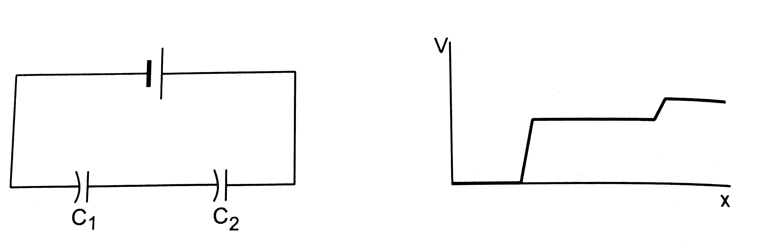
- Figure show two capacitors connected in series and joined to a battery...
Text Solution
|
- An uncharged capacitor is connected to a battery. Show that half the e...
Text Solution
|
- Figure show two capacitors connected in series and joind to a bettery....
Text Solution
|
- Figure shows two capacitors C1 and C2 connected with 10 V battery and ...
Text Solution
|
- A parallel plate capacitor has two layers of dielectric as shown in fi...
Text Solution
|
- Consider the situation as shown in figure. The variation of potential ...
Text Solution
|
- The figure shows a arrangement of capacitors and a battery. If the pot...
Text Solution
|
- A capacitor is charged using an external battery with a resistance x i...
Text Solution
|
- Figure shows a parallel plate capacitor and the current in the connect...
Text Solution
|