A
B
C
D
Text Solution
Verified by Experts
The correct Answer is:


Topper's Solved these Questions
ALTERNATING CURRENT
AAKASH INSTITUTE ENGLISH|Exercise Assignment (Section - C ) (Objective Type Questions) ( More than one option are correct)|2 VideosALTERNATING CURRENT
AAKASH INSTITUTE ENGLISH|Exercise Assignment (Section - D) (Linked Comprehension Type Questions)|3 VideosALTERNATING CURRENT
AAKASH INSTITUTE ENGLISH|Exercise Assignment (Section - A) ( Objective Type Questions ( One option is correct))|40 VideosATOMS
AAKASH INSTITUTE ENGLISH|Exercise ASSIGNMENT SECTION J (Aakash Challengers )|5 Videos
Similar Questions
Explore conceptually related problems
AAKASH INSTITUTE ENGLISH-ALTERNATING CURRENT -Assignment (Section - B) (Objective Type Questions (One option is correct))
- The mean value of current for one complete cycle of shown current supp...
Text Solution
|
- In a series LCR circuit, the total reactance is 4 Omega and resistance...
Text Solution
|
- An alternating current of 1.5 mA with angular frequency 100 rad/s flo...
Text Solution
|
- A transformer has 500 primary turns and 10 secondary turns If V(p) is...
Text Solution
|
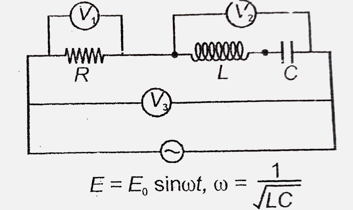
- In the circuit shown, the readings of voltmeters V(1), V(2) and V(3) a...
Text Solution
|
- In an LC circuit shown in figure, if the switch is closed at t = 0 , ...
Text Solution
|
- The inductance of a coil in which a current of 0.1 A increasing at the...
Text Solution
|
- The average value of an alternating voltage V=V(0) sin omega t over ...
Text Solution
|
- 10 kJ/s of heat is produced when a DC flows through a 100 Omega resist...
Text Solution
|
- If a direct current of value a ampere is superimposed on an alternatin...
Text Solution
|
- The average value of a saw-tooth voltage V=V(0) ((2t)/(T)-1) Over 0 ...
Text Solution
|
- An AC source of frequency omega when fed into a RC series circuit, cur...
Text Solution
|
- Alternating current may be termed as 'wattless' in case of
Text Solution
|
- The resonance curve for series LCR circuit is shown for three differen...
Text Solution
|