Text Solution
Verified by Experts


Topper's Solved these Questions
ELECTROSTATIC POTENTIAL AND CAPACITANCE
AAKASH INSTITUTE ENGLISH|Exercise ASSIGNMENT (SECTION-A) Objective Type Questions (Only one answer)|53 VideosELECTROSTATIC POTENTIAL AND CAPACITANCE
AAKASH INSTITUTE ENGLISH|Exercise SECTION-B (OBJECTIVE TYPE QUESTIONS (ONLY ONE ANSWER) )|1 VideosELECTROMAGNETIC WAVES
AAKASH INSTITUTE ENGLISH|Exercise ASSIGNMENT SECTION - D Assertion-Reason Type Questions|25 VideosGRAVITATION
AAKASH INSTITUTE ENGLISH|Exercise ASSIGNMENT SECTION - D (ASSERTION-REASON TYPE QUESTIONS)|15 Videos
Similar Questions
Explore conceptually related problems
AAKASH INSTITUTE ENGLISH-ELECTROSTATIC POTENTIAL AND CAPACITANCE -ASSIGNMENT SECTION - D
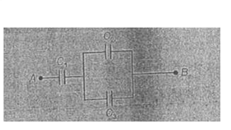
- In the arrangement C(1) = 10 mu, F C(2)= 10 mu F and C(3)= 20 mu F ....
Text Solution
|
- In the following question a statement of assertion (A) is followed by ...
Text Solution
|
- In the following question a statement of assertion (A) is followed by ...
Text Solution
|
- In the following question a statement of assertion (A) is followed by ...
Text Solution
|
- In the following question a statement of assertion (A) is followed by ...
Text Solution
|
- In the following question a statement of assertion (A) is followed by ...
Text Solution
|
- In the following question a statement of assertion (A) is followed by ...
Text Solution
|
- In the following question a statement of assertion (A) is followed by ...
Text Solution
|
- In the following question a statement of assertion (A) is followed by ...
Text Solution
|
- In the following question a statement of assertion (A) is followed by ...
Text Solution
|