Text Solution
Verified by Experts


Topper's Solved these Questions
CURRENT ELECTRICITY
AAKASH INSTITUTE ENGLISH|Exercise ASSIGNMENT SECTION-I(SUBJECTIVE TYPE QUESTIONS)|14 VideosCOMMUNICATION SYSTEMS
AAKASH INSTITUTE ENGLISH|Exercise ASSIGNMENT SECTION D (Assertion-Reason)|10 VideosDUAL NATURE OF RADIATION AND MATTER
AAKASH INSTITUTE ENGLISH|Exercise ASSIGNMENT (SECTION-D)|10 Videos
Similar Questions
Explore conceptually related problems
AAKASH INSTITUTE ENGLISH-CURRENT ELECTRICITY-ASSIGNMENT SECTION-J
- You have a microammeter which reads 50 muA at full scale deflection an...
Text Solution
|
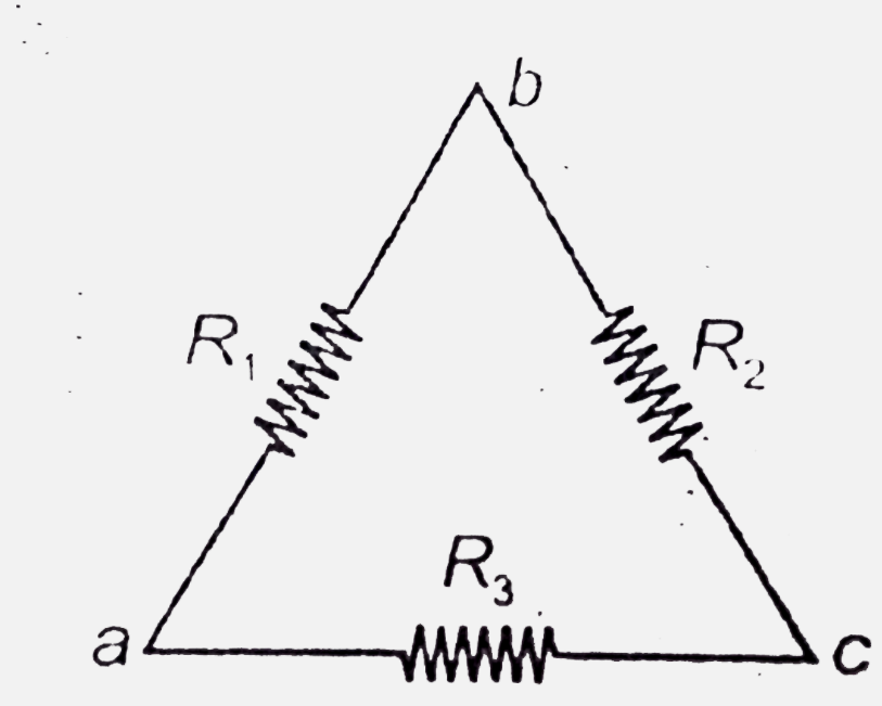
- Consider the circuit shown in the figure. Equivalent resistance betwee...
Text Solution
|
- Initially switch 'S' was open and the circuit has achieved its steady...
Text Solution
|
- In the circuit shown the capacitance of each capacitance is equal to C...
Text Solution
|
- Two metal balls of the same radius a are located in a homogeneous po...
Text Solution
|
- A rod of length L and cross-section area A lies along the x-axis betwe...
Text Solution
|
- If all the energy lost from joule heating stays in a wire , and the te...
Text Solution
|
- In a uniform solid cylinder of radius R conductivity increases linearl...
Text Solution
|
- Consider . The charge appearing is C(2) is.
Text Solution
|
- At t=0 switch S is closed . Find (i) Charge flown through switch (...
Text Solution
|