A
B
C
D
Text Solution
Verified by Experts
The correct Answer is:


Topper's Solved these Questions
ELECTROMAGNETIC INDUCTION
AAKASH INSTITUTE ENGLISH|Exercise ASSIGNMENT(SECTION - A) (OBJECTIVE TYPE QUESTIONS)|35 VideosELECTROMAGNETIC INDUCTION
AAKASH INSTITUTE ENGLISH|Exercise ASSIGNMENT(SECTION - B) (OBJECTIVE TYPE QUESTIONS)|25 VideosELECTROMAGNETIC INDUCTION
AAKASH INSTITUTE ENGLISH|Exercise Assignment (SECTION - J)|5 VideosELECTRIC CHARGES AND FIELDS
AAKASH INSTITUTE ENGLISH|Exercise comprehension|3 VideosELECTROMAGNETIC WAVES
AAKASH INSTITUTE ENGLISH|Exercise ASSIGNMENT SECTION - D Assertion-Reason Type Questions|25 Videos
Similar Questions
Explore conceptually related problems
AAKASH INSTITUTE ENGLISH-ELECTROMAGNETIC INDUCTION-EXERCISE
- As shown in the figure, à magnet is moved with a fast speed towards a ...
Text Solution
|
- A magnet N-S is suspended from a spring and while at oscillates, the m...
Text Solution
|
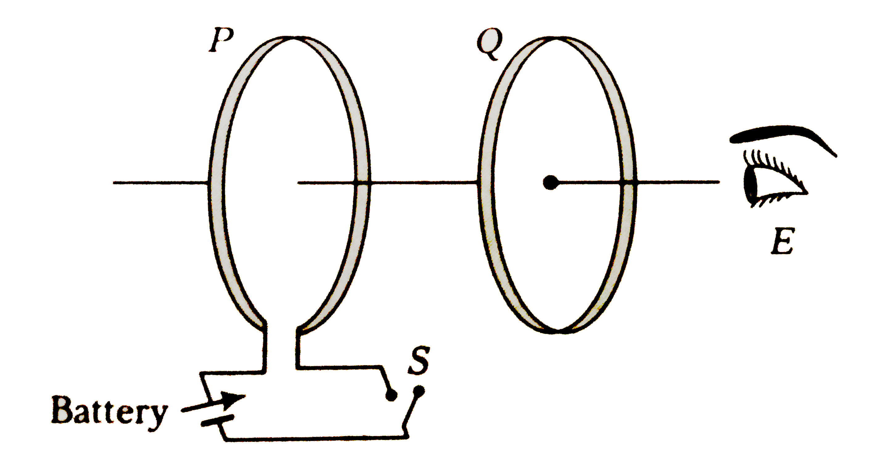
- As shown in figure, P and Q are two co-axial conducting loops separate...
Text Solution
|
- Two different loops are concentric and lie in the same plane. The curr...
Text Solution
|
- The direction of induced currnet in the right loop in the situation sh...
Text Solution
|
- An aluminium ring B faces an electromagnet A. The current I through A ...
Text Solution
|
- A conducting wire frame is placed is placed in a magnetic field which ...
Text Solution
|
- A vertical rod of length l is moved with constant velocity v towards e...
Text Solution
|
- The current carrying wire and the rod AB are in the same plane. The ro...
Text Solution
|
- A helicopter rises vertically upwards with a speed of 100 m//s. If the...
Text Solution
|
- A rod AB slides on a V shaped wire with speed v as shown, such that at...
Text Solution
|
- if given arrangement is moving towards left with speed v, then potenti...
Text Solution
|
- A conducting rod is rotated about one end in a plane perpendicular to ...
Text Solution
|
- A semicircular loop of radius R is rotated with an angular velocity om...
Text Solution
|
- A force of 10N is required to move a conducting loop through a non-uni...
Text Solution
|
- A flexible wire bent in the form of a circle is placed in a uniform ma...
Text Solution
|
- Radius ol a circular luop placed in a perpendicular uniform magnetic f...
Text Solution
|
- A wire of fixed length is wound on a solenoid of length 'l' and radius...
Text Solution
|
- The length of thin wire required to manufacture a solenoid of inductan...
Text Solution
|
- A conducting ring of radius b is placed coaxially in a long solenoid o...
Text Solution
|