A
B
C
D
Text Solution
Verified by Experts
The correct Answer is:


Similar Questions
Explore conceptually related problems
Recommended Questions
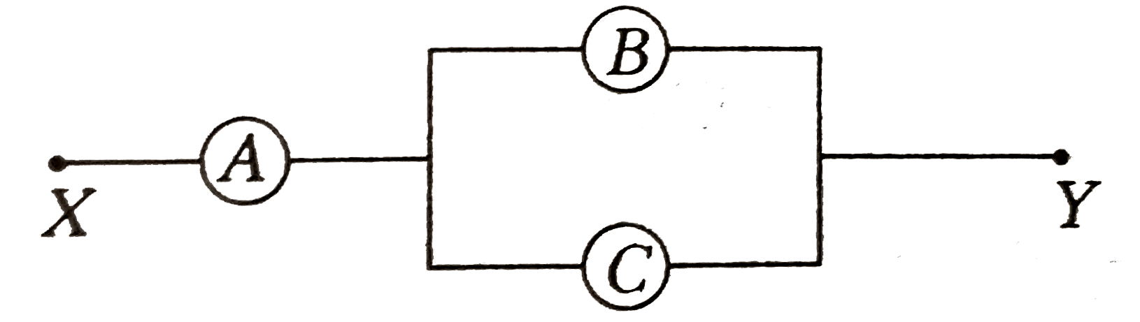
- A, B and C are voltmeters of resistance R, 1.5 R and 3R respectively, ...
Text Solution
|
- A, B and C are voltmeters of resistances R, 1.5R and 3R respectively. ...
Text Solution
|
- आरेख में दिखाये गये वोल्टमीटरों A , B तथा C के प्रतिरोध क्रम...
Text Solution
|
- यदि किसी L-C-R परिपथ में V(L), V(R),V(C) तथा V(0) क्रमशः प्रेरकत्व, प्...
Text Solution
|
- A,B and C are voltmeters of resistance R, 1.5 R and 3R respectively as...
Text Solution
|
- Three voltmeters A, B and C having resistances R, 1.5 R and 3 R respec...
Text Solution
|
- The voltmeters A,B, and C having resistance R, 1.5R and 3R respectivel...
Text Solution
|
- A, B and C arc voltmeters of resistance R, 1.5R and 3R respectively as...
Text Solution
|
- A,B and C are voltmeters of resistance R, 1.5 R and 3R respectively as...
Text Solution
|