Home
Class 12
PHYSICS
For a cell, a graph is plotted between t...

For a cell, a graph is plotted between the potential difference V across the terminals of the cell and the current I drawn the cell. The emf and the internal resistance of the cell are E and r, respectively. Then

A

E = 2 V, `r = 0.5 Omega`

B

E= 2 V, `r =0.4 Omega`

C

Egt 2 V, `r = 0.5 Omega`

D

E gt 2 V, `r = 0.4 Omega`

Text Solution

Verified by Experts

The correct Answer is:
B
Promotional Banner

Topper's Solved these Questions

  • MOCK TEST 9

    AAKASH INSTITUTE ENGLISH|Exercise Example|105 Videos
  • MOCK_TEST_17

    AAKASH INSTITUTE ENGLISH|Exercise Example|15 Videos

Similar Questions

Explore conceptually related problems

For a cell, the graph between the potential difference (V) across the terminals of the cells and the current I drawn from the cell is as shown in figure. Calculate the e.m.f. and the internal resistance of the cell.

What is the relationship between potential difference across the terminals of a cell and emf of the cell ?

What is the relationship between potential difference across the terminalsof a cell and emf of the cell?

For the determination of emf E and internal resistance 'r' of a cell , the graph is obtained between potential difference V between the terminal of the cell against the current l, which was changed by adjusting the rheostat, is as shown . The internal resistance of the cell is

A cell of emf E is connected across a resistance R. The potential difference between the terminals of the cell is found to be V. The internal resistance of the cell must be -

In an experiment, a graph was plotted of the potential difference V between the terminals of a cell against the circuit current "I" by varying load rheostat, internal conductance of the cell is given by

In a network as shown in the figure , the potential difference across the resistance 2 R is (the cell has emf E - volt and no internal resistance )

In the situation shown , the potential difference across the cell of smaller e.m.f is .

Find the current drawn from a cell of emf 2 V and internal resistance 2 Omega connected to the network given below.

A cell of emf epsilon and internal resistance r is charged by a current I, then

AAKASH INSTITUTE ENGLISH-Mock Test27-EXAMPLE
  1. If the power dissipated in the 27 Omega resistor in the circuit shown ...

    Text Solution

    |

  2. The resistance between the lerminal points P and Q of the given infini...

    Text Solution

    |

  3. A battery of EMF 10 V, with internal resistance 1 Omega is being charg...

    Text Solution

    |

  4. A battery of EMF E produces currents 4 A and 3 A when connected to ext...

    Text Solution

    |

  5. A 5 V battery with internal resistance 1 Omega and a 2 V battery with...

    Text Solution

    |

  6. n identical cells each of e.m.f. E and internal resistance r are conne...

    Text Solution

    |

  7. Two sources of equal emf are connected to an external resistance R. Th...

    Text Solution

    |

  8. A cell of internal resistance r drivers current through an external r...

    Text Solution

    |

  9. To get maximum current through a resistance of 2.5Omega, one can use ...

    Text Solution

    |

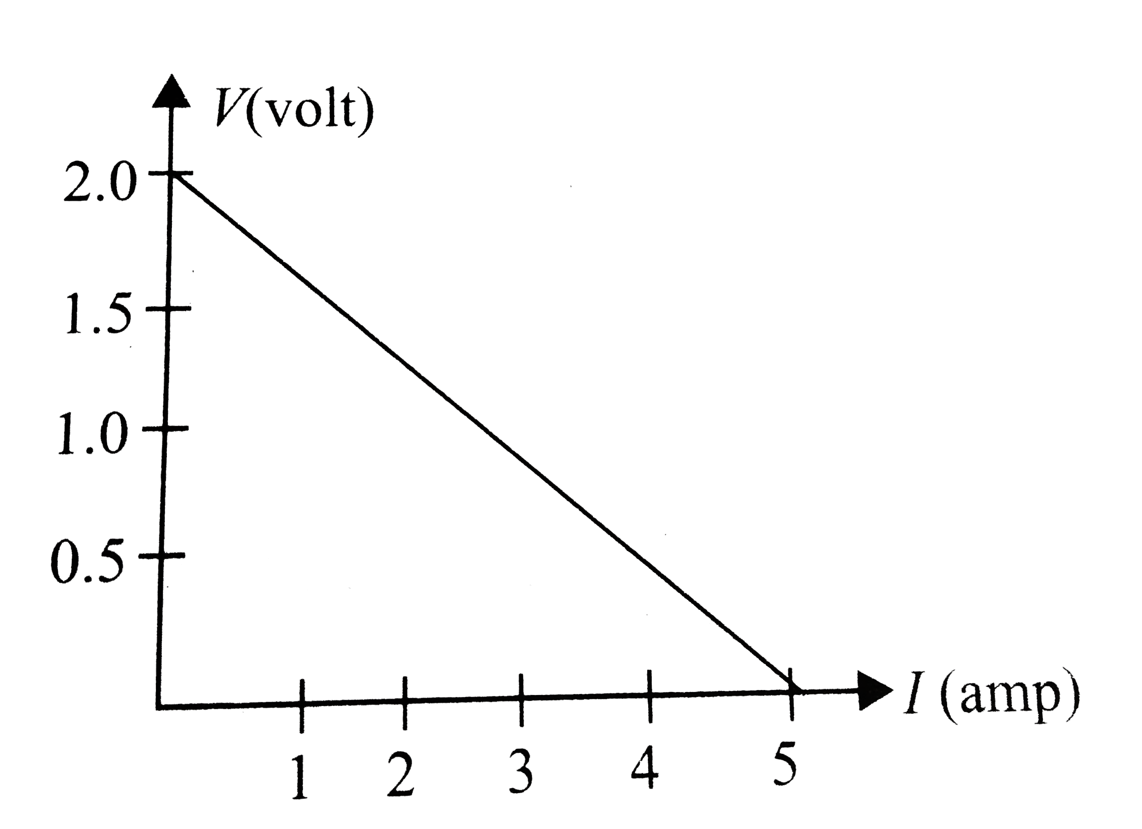
  10. For a cell, a graph is plotted between the potential difference V acro...

    Text Solution

    |

  11. If electric bulbs having resistances in the ratio 2 : 3 are connected ...

    Text Solution

    |

  12. Two bulbs 100 W, 250 V and 200 W, 250 V are connected in parallel acro...

    Text Solution

    |

  13. Fill in the blanks :

    Text Solution

    |

  14. The following figure shows a part of a circuit,the potential differenc...

    Text Solution

    |

  15. In the given circuit. If the potential at A is 95 V, then the potentia...

    Text Solution

    |

  16. Shown is a network of currents. The magnitude of the current is also s...

    Text Solution

    |

  17. The following figure shows a part of a circuit,the potential differenc...

    Text Solution

    |

  18. Potential different across the terminals of the battery shown in figur...

    Text Solution

    |

  19. As the switch S is closed in the circuit shown in figure, current pass...

    Text Solution

    |

  20. The following figure shows a part of a circuit,the potential differenc...

    Text Solution

    |