Home
Class 12
PHYSICS
As shown in diagram, a current carrying ...

As shown in diagram, a current carrying conductor is subjected to steady uniform magnetic field. Then

A

Torque T = 0, force F= 0

B

`Torque T !=0` ,`force F !=0`

C

Torque T = 0 , `force F !=0`

D

`Torque T !=0` , force F= 0

Text Solution

Verified by Experts

Promotional Banner

Topper's Solved these Questions

  • TEST 1

    AAKASH INSTITUTE ENGLISH|Exercise EXERCISE|21 Videos
  • TEST 3

    AAKASH INSTITUTE ENGLISH|Exercise EXAMPLE|74 Videos

Similar Questions

Explore conceptually related problems

A current carrying coil is subjected to a uniform magnetic field. The coil will orient so that its plane become

A current carrying coil is subjected to a uniform magnetic field. The coil will orient so that its plane become

A coil carrying electric current is placed in uniform magnetic field

The figure shows a long straight current carrying conductor. Can you plot the variation of magnetic field on x-axis ?

Assertion : A current carrying loop is placed in uniform magnetic field as shown in figure. Torque in the loop in this case is zero. Reason : Magnetic moment vector of the loop is perpendicular to paper inwards.

A conductor (shown in the figure) carrying constant current I is kept in the x-y plane in a uniform magnetic field B. If F is the magnitude of the total magnetic force acting on the conductor, then the correct statement is/are

A conductor (shown in the figure) carrying constant current I is kept in the x-y plane in a uniform magnetic field vec(B) . If vec(F) is the magnitude of the total magnetic force acting on the conductor, then the correct statement(s) is (are)

The direction of force on a current carrying conductor in a magnetic field is given by

Draw the pattern of magnetic field lines around a current carrying strainght conductor. How does the strength of the magnetic field produced change. (i) with the distance from the conductor ? (ii) with increase in current in a conductor ?

A current carrying loop is free to turn in a uniform magnetic field. The loop will then come into equilibrium vhen its plane is inclined at

AAKASH INSTITUTE ENGLISH-TEST 2-Exercise
  1. A charge particle of mass m and charge q is projected with velocity v ...

    Text Solution

    |

  2. In cyclotron, dees are perforated so that the stream of particles move...

    Text Solution

    |

  3. As shown in diagram, a current carrying conductor is subjected to stea...

    Text Solution

    |

  4. Electric field and magnetic field in a region of space are given by(Ē=...

    Text Solution

    |

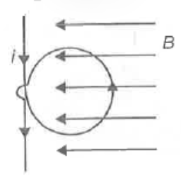
  5. A circular flexible loop of wire of radius r carrying a current I is p...

    Text Solution

    |

  6. A closed loop carrying current is placed so that its plane is perpendi...

    Text Solution

    |

  7. An electron with mass m, velocity v and charge e describe half a revol...

    Text Solution

    |

  8. A conducting wire MN moves with velocity V0 along +X-axis in a uniform...

    Text Solution

    |

  9. As shown in figure there is a ring having radius R and charge q distri...

    Text Solution

    |

  10. Two non-interacting inductor L1 = 2 mH and L2 = 5 mH are connected in ...

    Text Solution

    |

  11. A square loop of side 10 cm with its side parallel to X, and y axis is...

    Text Solution

    |

  12. A conducting rod PQ is rotated in a magnetic field B about an axis pas...

    Text Solution

    |

  13. A magnet is suspended in the magnetic meridian with an untwisted wire....

    Text Solution

    |

  14. A bar magnet has a coercivity of (4000 Am^-1) It is desired to demagne...

    Text Solution

    |

  15. A short bar magnet of magnetic moment 1.5 Am^2 is placed along x-axis ...

    Text Solution

    |

  16. A parallel plate capacitor made of circular plates each of radius 6 cm...

    Text Solution

    |

  17. A coil in the shape of square is placed in a variable magnetic field, ...

    Text Solution

    |

  18. A uniform magnetic field along a long cylindrical rod varies with time...

    Text Solution

    |

  19. The network shown in the figure is a part of a complete circuit. If at...

    Text Solution

    |

  20. The time constant for LR circuit between the terminals a and b as show...

    Text Solution

    |