A
B
C
D
Text Solution
Verified by Experts
The correct Answer is:


Topper's Solved these Questions
DAILY PRACTICE PROBLEM
RESONANCE ENGLISH|Exercise DPP No.49|20 VideosDAILY PRACTICE PROBLEM
RESONANCE ENGLISH|Exercise DPP No.50|9 VideosDAILY PRACTICE PROBLEM
RESONANCE ENGLISH|Exercise DPP No.47|20 VideosCURRENT ELECTRICITY
RESONANCE ENGLISH|Exercise High Level Problems (HIP)|19 VideosELECTRO MAGNETIC WAVES
RESONANCE ENGLISH|Exercise Exercise 3|27 Videos
Similar Questions
Explore conceptually related problems
RESONANCE ENGLISH-DAILY PRACTICE PROBLEM-DPP No.48
- A light cylindrical tube T of length l and radius r containing air is ...
Text Solution
|
- For the given electromagnetically coupled circuits: (S is initially in...
Text Solution
|
- In the arrangement shown, a potential difference is applied between po...
Text Solution
|
- Two concentric rings of radii R(1) = sqrt(6) m and R(2) = 4m are place...
Text Solution
|
- The current density vecj inside a long, solid, cylindrica wire of radi...
Text Solution
|
- A particle is projected from point A, that is at a distance 4R form th...
Text Solution
|
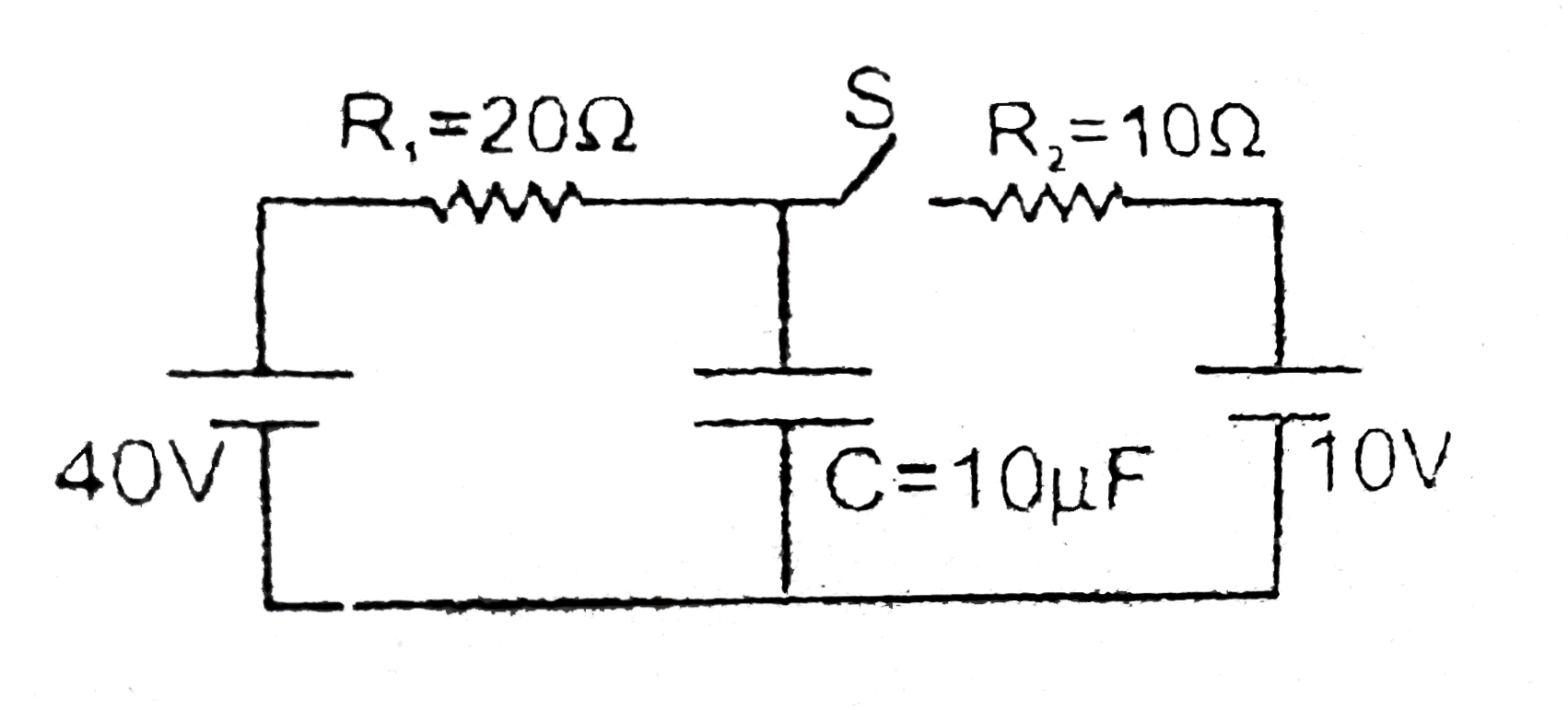
- The circuit consists of two resistors (of resistance R(1) = 20 Omega a...
Text Solution
|
- The circuit consists of two resistors (of resistance R(1) = 20 Omega a...
Text Solution
|
- The circuit consists of two resistors (of resistance R(1) = 20 Omega a...
Text Solution
|