A
B
C
D
Text Solution
Verified by Experts
The correct Answer is:


Topper's Solved these Questions
Similar Questions
Explore conceptually related problems
RESONANCE ENGLISH-ALTERNATING CURRENT-Exercise -2 Part-4
- A voltage source V=V(0) sin (100 t) is connected to a black box in whi...
Text Solution
|
- A voltage source V=V(0) sin (100 t) is connected to a black box in whi...
Text Solution
|
- A voltage source V=V(0) sin (100 t) is connected to a black box in whi...
Text Solution
|
- An ac generator G with an adjustable frequency of oscillation is used ...
Text Solution
|
- An ac generator G with an adjustable frequency of oscillation is used ...
Text Solution
|
- An ac generator G with an adjustable frequency of oscillation is used ...
Text Solution
|
- An ac generator G with an adjustable frequency of oscillation is used ...
Text Solution
|
- An ac generator G of 100 V rms value with an adjustable frequency of o...
Text Solution
|
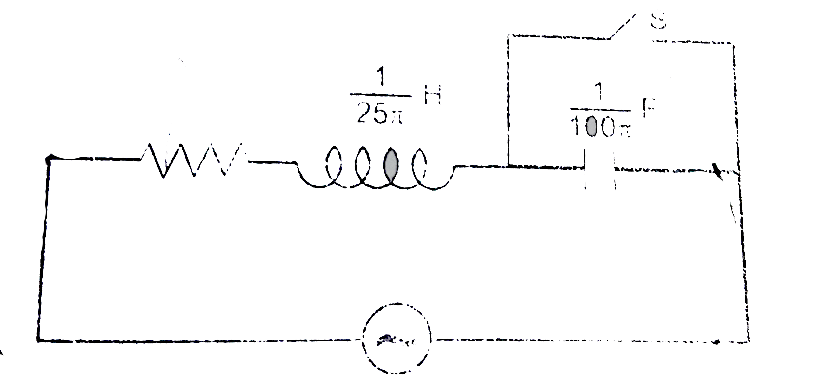
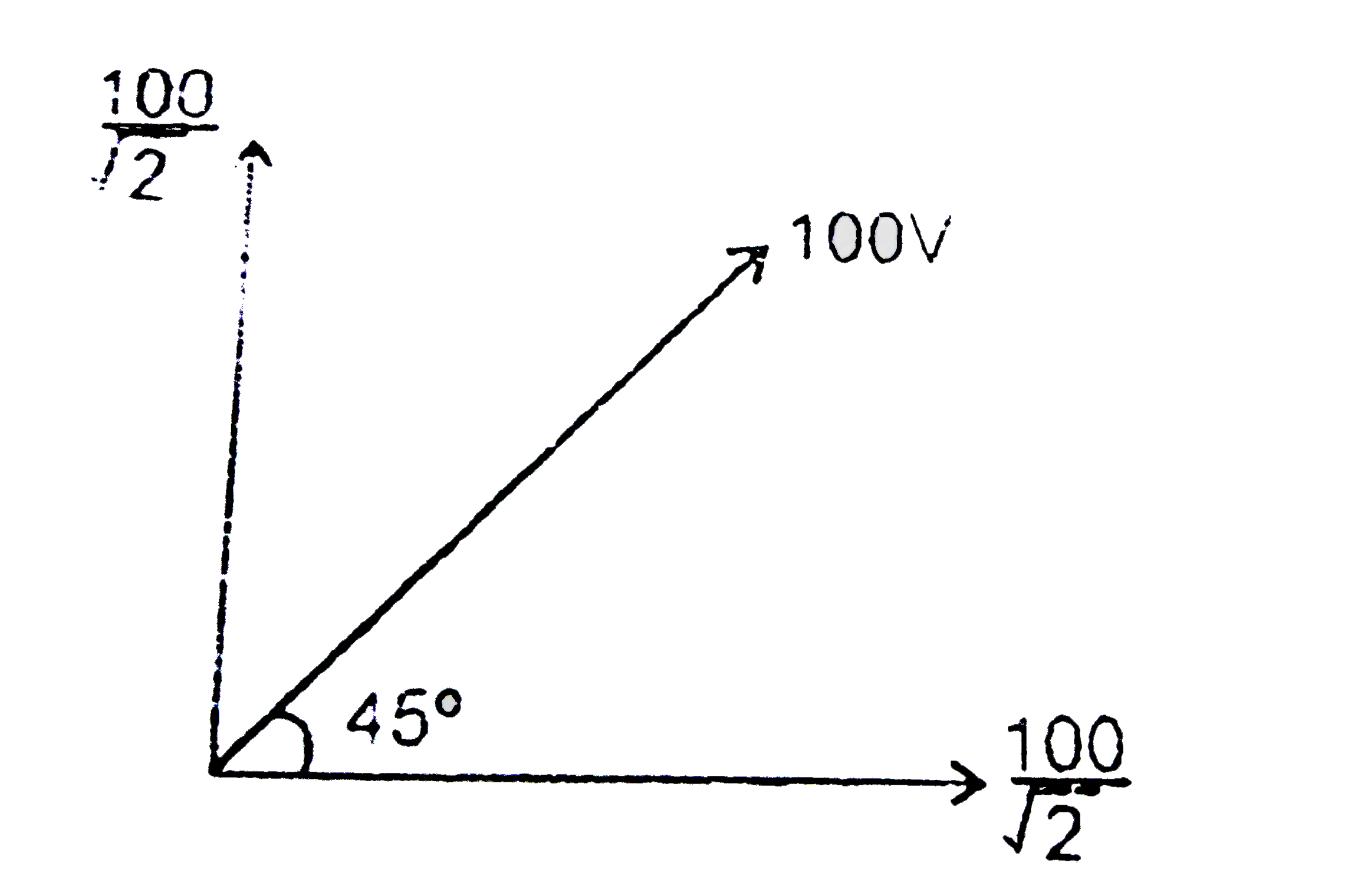
- In the LCR circuit shown in figure unknown resistance and alternating ...
Text Solution
|
- In the LCR circuit shown in figure unknown resistance and alternating ...
Text Solution
|
- In the LCR circuit shown in figure unknown resistance and alternating ...
Text Solution
|