A
B
C
D
Text Solution
Verified by Experts
The correct Answer is:


Topper's Solved these Questions
CAPACITANCE
RESONANCE ENGLISH|Exercise Exercise - 2|74 VideosCAPACITANCE
RESONANCE ENGLISH|Exercise Exercise - 3|26 VideosCAPACITANCE
RESONANCE ENGLISH|Exercise Miscellaneous Solved Example|3 VideosATOMIC PHYSICS
RESONANCE ENGLISH|Exercise Advanved level problems|17 VideosCOMMUNICATION SYSTEMS
RESONANCE ENGLISH|Exercise Exercise 3|13 Videos
Similar Questions
Explore conceptually related problems
RESONANCE ENGLISH-CAPACITANCE-Exercise - 1
- A generator has an EMF of 440 V and internal resistance of 400 ohm . I...
Text Solution
|
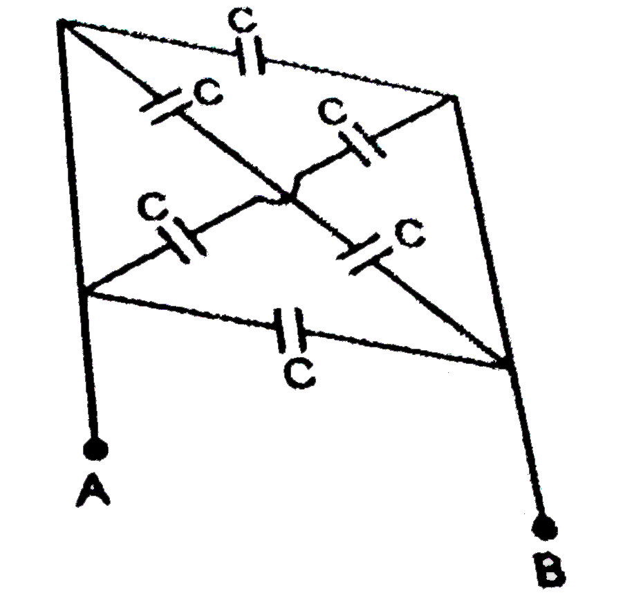
- In the adjoining circuit, the capacity between the points A and B will...
Text Solution
|
- The resultant capacity between the points A and B in the adjoining cir...
Text Solution
|
- The effective capacity with the following figure between the points P ...
Text Solution
|
- The equivalent capacitance between the terminals X and Y in the figure...
Text Solution
|
- The minimum number of condensers each capacitance of 2 muF, in order t...
Text Solution
|
- The charge on the condenser of capacitance 2mu F in the following circ...
Text Solution
|
- Two parallel plate condensers of capacity 20 mF and 30 mF are charged ...
Text Solution
|
- Seven capacitors, each of capacitance 2 muF, are to be combined to obt...
Text Solution
|
- In the circuit shown below the switch is closed at t=0. For 0 lt t lt...
Text Solution
|
- A capacitor of capacitance C is charged to a potential difference V(0)...
Text Solution
|
- A 3 mega ohm resistor and an uncharged 1 mu F capacitor are connecte...
Text Solution
|
- A 3 mega ohm resistor and an uncharged 1 mu F capacitor are connecte...
Text Solution
|
- A 3 mega ohm resistor and an uncharged 1 mu F capacitor are connecte...
Text Solution
|
- A 3 mega ohm resistor and an uncharged 1 mu F capacitor are connecte...
Text Solution
|
- A capacitor of capacitance 8.0(mu)F is connected to a bettery of emf 6...
Text Solution
|
- A capacitor of capacitance 8.0(mu)F is connected to a bettery of emf 6...
Text Solution
|
- An uncharged capacitor of capacitance 100 mu F is connected to a bat...
Text Solution
|
- An uncharged capacitor of capacitance 100 mu F is connected to a bat...
Text Solution
|
- The charge on each of the capacitors 0.16 ms after the switch S is c...
Text Solution
|