A
B
C
D
Text Solution
Verified by Experts
The correct Answer is:


Similar Questions
Explore conceptually related problems
Recommended Questions
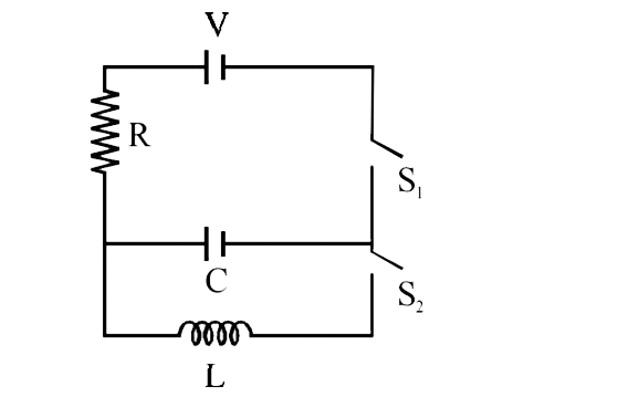
- In an LCR circuit as shown below both switches are open initially. Now...
Text Solution
|
- In an LCR circuit as shown below both switches are open initially. Now...
Text Solution
|
- In the given circuit, the initial charges on the capacitors are shown ...
Text Solution
|
- In the circuit shown, the capacitor is initially charged with a 12V ba...
Text Solution
|
- In the circuit shown, the capacitor initially charged with a 12V batte...
Text Solution
|
- The capacitor of capacitance C can be charged (with the help of a resi...
Text Solution
|
- As shown in diagram initial charge on capacitor is zreo . Now switch S...
Text Solution
|
- In the circuit given below, the capacitor C is charged by closing the ...
Text Solution
|
- नीचे दिए गए एक LCR परिपथ में प्रारंभ में दोनों स्विच खुले हैं। अब स्वि...
Text Solution
|