Home
Class 12
PHYSICS
In the circuit shown in the figure, the...

In the circuit shown in the figure, there are two prallel plate capacitors each of capacitance C. The switch `S_1` is pressed first to fully charge the capacitor `C_1` and then released. The switch S is then pressed to charge the capacitor `C_2`. After some time, `S_2` is released and then S is pressed. After some time,

A

The charge on the upper plate of `C_(1) is 2CV_(0)`

B

The charge on the upper plate of `C_(1) is CV_(0)`

C

The charge on the upper plate of `C_(2) is 0`

D

The charge on the upper plate of `C_(2) is -CV_(0)`

Text Solution

Verified by Experts

The correct Answer is:
B, D

After pressing `S_1` chare on upper plate `c_1` is `cv_0`.After pressing `S_2` this charge equally distributes in two capicators. Therefore charge on upper plates of both capacitor will be `+CV_0`. When `S_2` is released and `S_2`pressed,charge on upper plate of `c_1` remains unchanged `(=+cv_0)` but charge on upper plate of is according to new battery `(=-cv_0)`
Doubtnut Promotions Banner Mobile Dark
|

Topper's Solved these Questions

  • CAPACITORS

    VMC MODULES ENGLISH|Exercise JEE Advance ( Archive ) LEVEL 26|1 Videos
  • CAPACITORS

    VMC MODULES ENGLISH|Exercise JEE Advance ( Archive ) LEVEL 27|1 Videos
  • CAPACITORS

    VMC MODULES ENGLISH|Exercise JEE Advance ( Archive ) LEVEL 24|1 Videos
  • BASIC MATHEMATICS & VECTORS

    VMC MODULES ENGLISH|Exercise Impeccable|50 Videos
  • CURRENT ELECTRICITY

    VMC MODULES ENGLISH|Exercise IN-CHAPTER EXERCISE-F|10 Videos

Similar Questions

Explore conceptually related problems
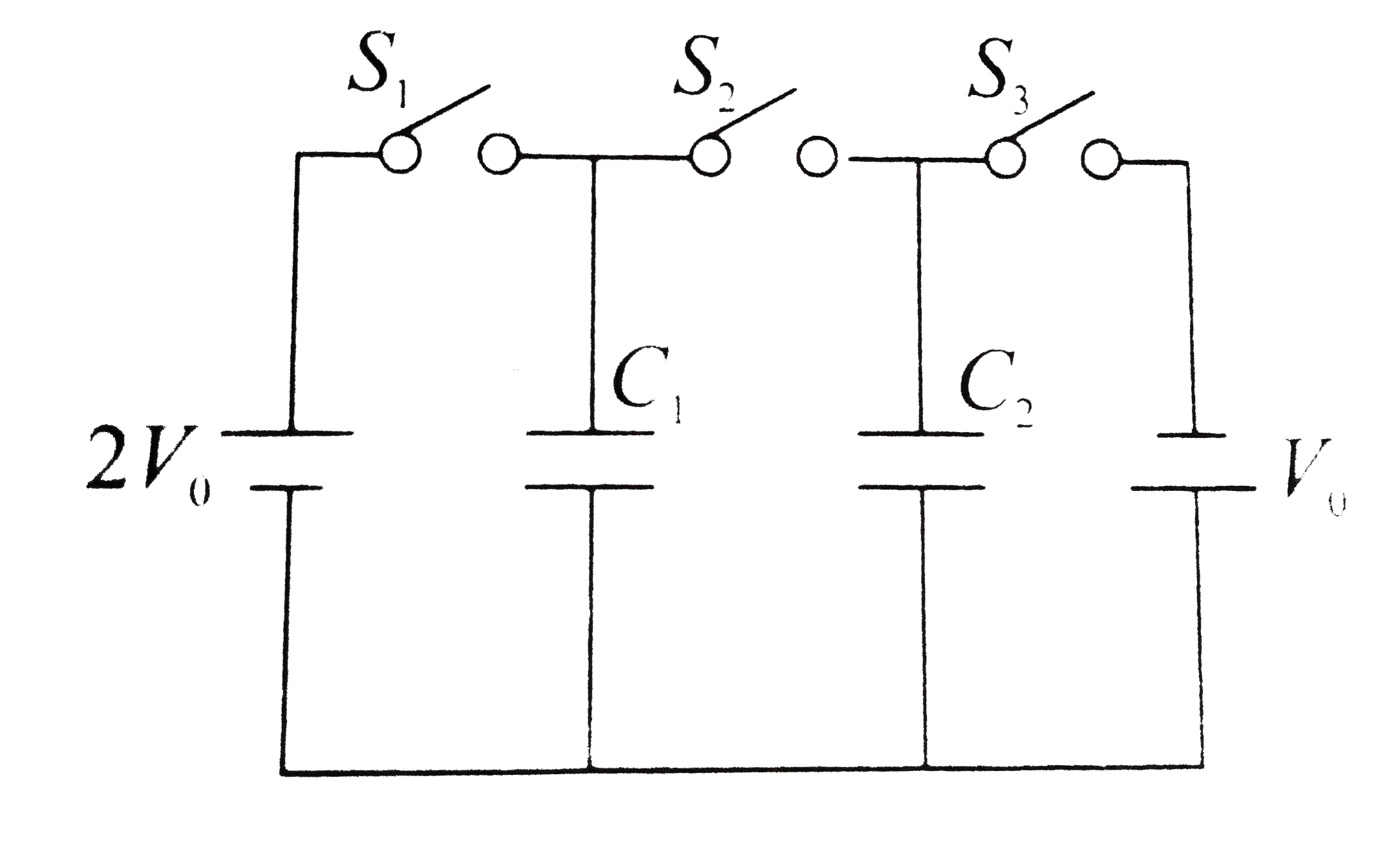
In the circuit shown in the figure, there are two parallel plate capacitors each of capacitance C. The switch S_1 is pressed first to fully charge the capacitor C_1 and then released. The switch S_2 is then pressed to charge the capacitor C_2 . After some time, S_2 is released and then S_3 is pressed. After some time

In the circuit shown in fig. when the switch is closed, the capacitor charges with a time constant

In the R-C circuit shown in the figure the total of 3.6 xx 10^(-3)J is dissipated in the 10 ohms resistor when the switch S is closed. The initial charge on the capacitor is

Find the charge on each of the capacitor 0.20ms after the switch S is closed in Figure.

In the circuit shown in figure, the capacitor is charged with a cell of 5V .If the switch is closed at t=0 , then at t=12s , charge on the capacitor is

In the circuit shown, each capacitor has a capacitance C. The emf of the cell is E. If the switch S is closed

In the circuit shown in fig, if the switch S is closed at t = 0 , the capacitor charges with a time constant

The charge on each of the capacitors 0.16 ms after the switch S is closed in figure is :

The switch S in the circuit diagram is closed at t = 0. The charge on capacitors at any time is

The time constant, for charging of capacitor C, when switch S is closed as shown in the figure , is