A
B
C
D
Text Solution
Verified by Experts


Topper's Solved these Questions
Similar Questions
Explore conceptually related problems
VMC MODULES ENGLISH-DC CIRCUIT-JEE ADVANCED ARCHIVE
- A wire of length L and three identical cell of negligible internal res...
Text Solution
|
- A 100 W bulb B1, and two 60 W bulbs B2 and B3 are connected to a 250 ...
Text Solution
|
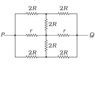
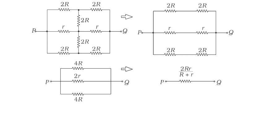
- The effective resistance between points P and Q of the electrical circ...
Text Solution
|
- The three resistances of equal values are arranged in different combin...
Text Solution
|
- In the shows arrangement of a meter bridge, if AC corresponding to nul...
Text Solution
|
- Express which of the following setups can be used to verify Ohm's law?
Text Solution
|
- Six equal resistances are connected between points P, Q and R as shown...
Text Solution
|
- Find out the value of current through 2Omega resistance for the given...
Text Solution
|
- An ideal gas is filled in a closed rigid and thermally insulated conta...
Text Solution
|
- Two bars of equal resistivity rho and radius 'r' and '2r' are kept in ...
Text Solution
|
- A resistance of 2Omega is connected across one gap of a meter bridge (...
Text Solution
|
- Figure shows three resistor configurations R1,R2 and R3 connected to 3...
Text Solution
|
- Statement I: In a meter bridge experiment, null point for an unknown r...
Text Solution
|
- A moving coil galvanometer of resistance 100Omega is used as an ammete...
Text Solution
|
- To verify Ohm's law, a student is provided with a test resistor R(T), ...
Text Solution
|
- Consider a thin square sheet of side L and thicknest, made of a materi...
Text Solution
|
- Incandescent bulbs are designed by keeping in mind that the resistance...
Text Solution
|
- A meter bridge is set- up as shown in figure, to determine an unknown ...
Text Solution
|
- In an aluminium (Al) bar of square cross section, a square hole is dri...
Text Solution
|
- An infinite line charge of uniform electric charge density lambda lies...
Text Solution
|