Home
Class 12
PHYSICS
Two ideal batteries of emf V1 and V2 and...

Two ideal batteries of emf `V_1 and V_2` and three resistances `R_1, R_2 and R_3` are connected as shown in the figure. The current in resistance `R_2` would be zero if

A

`V_1=V_2 and R_1= R_2=R_3`

B

`V_1=V_2 and R_1=2R_2=R_3`

C

`V_1=2V_2 and 2R_1=2R_2=R_3`

D

`2V_1=V_2 and 2R_1=R_2=R_3`

Text Solution

Verified by Experts

From loop 1 `R_2+V_1=0`
`implies iR_1+i_1R_2=V_1`……(i)
From loop 2
`i_1R_2-(i-i_1)R_3=-V_2`
`i_1(R_2+R_3)-iR_3=V_2`………(ii)
Solving equation (i) and (ii)
`i_1(R_2+R_3)-iR_3=-V_2 times R_1`
`i_1R_2+iR_1=V_1 times R_3`
`i_1(R_1R_2+R_1R_3+R_2R_3`
We get `i_1=(V_1R_3-V_2R_1)/(R_1+R_2+R_1R_3+R_2R_3`,
If `i_1` is zero
`V_1R_3=V_2R_1`
It is possible in followin options
(a) `V_1=V_2 implies R_1=R_3` (b) `V_1=V_2 implies R_1=R_3`
Promotional Banner

Topper's Solved these Questions

  • DC CIRCUIT

    VMC MODULES ENGLISH|Exercise LEVEL-1 JEE MAIN ARCHIVE|93 Videos
  • CURRENT ELECTRICITY

    VMC MODULES ENGLISH|Exercise IN-CHAPTER EXERCISE-F|10 Videos
  • DYNAMICS OF A PARTICLE

    VMC MODULES ENGLISH|Exercise JEE Advance (Archive) Level - II (SINGLE OPTION CORRECT TYPE )|31 Videos

Similar Questions

Explore conceptually related problems

Two ideal batteries of emf V_(1) and V_(2) and three resistance R_(1)R_(2) and R_(3) are connected The current in resistance R_(2) would be zero if

The given circuit has two ideal diodes connected as shown in the figure below. The current flowing through the resistance R_(1) will be

Two batteries of emf E_(1) and E_(2)(E_(2) gt E_(1)) and internal resistance r_(1) and r_(2) respectively are connected in parallel as shown in the figure. Then, which of the followings statements is correct ?

Two non-ideal batteries have e.m.f 2V and 8V respective ly and internal resistance 1 Omega and 2 Omega respectively as shown in the figure. If the potential difference between a and b is zero then the resistance R has a value

Two batteries of emf 4 V and 8 V with internal resistances 1Omega and 2Omega are connected in a circuit with a resistance of 9Omega as shown in figure. The current and potential difference between the points P and Q are

Two indentical batteries, each of emf 2V andinternal resistance r=1Omega are connected as shown. The maximum power that can be developed across R using these batteries is

An inductor of inductance L=400 mH and resistors of resistances R_1=2Omega and R_2=2Omega are connected to a battery of emf E=12 V as shown in the figure. The internal resistance of the battery is negligible. The switch S is closed at time t=0 . What is the potential dro across L s a function of time? After the steady state is reached, the switch is opened. What is the direction ad the magnitude of current throough R_1 as a function of time?

An inductor of inductance L = 400 mH and resistors of resistance R_(1) = 2Omega and R_(2) = 2Omega are connected to a battery of emf 12 V as shown in the figure. The internal resistance of the battery is negligible. The switch S is closed at t = 0 . The potential drop across L as a function of time is

An inductor of inductance L = 400 mH and resistors of resistance R_(1) = 2Omega and R_(2) = 2Omega are connected to a battery of emf 12 V as shown in the figure. The internal resistance of the battery is negligible. The switch S is closed at t = 0 . The potential drop across L as a function of time is

VMC MODULES ENGLISH-DC CIRCUIT-JEE ADVANCED ARCHIVE
  1. For the resistance network shown in the figure, choose the correct opt...

    Text Solution

    |

  2. Heater of an electric kettle is made of a wire of length L and diamete...

    Text Solution

    |

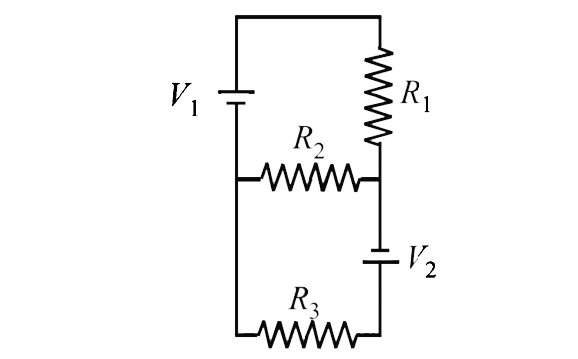
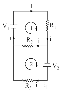
  3. Two ideal batteries of emf V1 and V2 and three resistances R1, R2 and ...

    Text Solution

    |

  4. An incandesent bulb has a thin filament of tungsten that is heated to ...

    Text Solution

    |

  5. Consider two identical galvanometers and two identical resistors with ...

    Text Solution

    |

  6. Two identical moving coil galvanometers have 10Omega resistance and f...

    Text Solution

    |

  7. Consider an evacuated cylindrical chamber of height h having rigid con...

    Text Solution

    |

  8. Consider an evacuated cylindrical chamber of height h having rigid con...

    Text Solution

    |

  9. Each of the resistance in the network shown in the figure is equal to ...

    Text Solution

    |

  10. A copper wire iis stretched to make it 0.1% longer. What is the percen...

    Text Solution

    |

  11. A heater is designed to operate with a power of 1000 W in a 100 V line...

    Text Solution

    |

  12. A copper wire having cross- sectional area of 0.5 mm^2 and a length of...

    Text Solution

    |

  13. A copper wire having cross- sectional area of 0.5 mm^2 and a length of...

    Text Solution

    |

  14. All resistance in the diagram are in ohm Find the effective resistan...

    Text Solution

    |

  15. A battery of emf 2.0 V and internal resistance 0.10 Omega is being cha...

    Text Solution

    |

  16. In the circuit, a voltmeter reads 30 V when it is connected across 400...

    Text Solution

    |

  17. In the circuit in figure E1=3V, E2=2V, E3=1V and R=r1=r2=r3=1Omega ...

    Text Solution

    |

  18. In the circuit shown, E, F, G and H are cells of emf 2V, 1V, 3V and 1V...

    Text Solution

    |

  19. An infinite ladder is constructed with 1(Omega)and 2(Omega)resistor as...

    Text Solution

    |

  20. An electrical circuit is shown in figure. Calculate the potential diff...

    Text Solution

    |