Home
Class 12
PHYSICS
In the circuit shown, E, F, G and H are ...

In the circuit shown, E, F, G and H are cells of emf 2V, 1V, 3V and 1V respectively and their internal resistances are `2 Omega, 1 Omega, 3 Omega` and `1 Omega` respectively.

Text Solution

Verified by Experts

(i) `2/13 V, (ii) V_G=21/13V, V_H=9/13V`
Applying kirchoff's second law in loop BADB, `2-2j_1-j_1-1-2(j_1-j_2)=0`
Similarly applying kirchoff's second law in loop BDCB
`2(j_1-j_2)+3-3j_2-j_2-1=0`………(ii)
Solving Eqs. (i) and (ii) we get
`j_1=5/13,j_2=6/13 and j_1-j_2=-1/13`
(i) Potential difference between B and D,
`V_B+2(j_1-j_2)=V_D`
`therefore V_B-V_D=-2(j_1-j_2)=2/13 V`
(ii) `V_G=E_G-j_2r_G=3-6/13 times 3=21/13 V, V_H=E_H+j_2r_h=1+6/13 times 1=19/13V`
Promotional Banner

Topper's Solved these Questions

  • DC CIRCUIT

    VMC MODULES ENGLISH|Exercise LEVEL-1 JEE MAIN ARCHIVE|93 Videos
  • CURRENT ELECTRICITY

    VMC MODULES ENGLISH|Exercise IN-CHAPTER EXERCISE-F|10 Videos
  • DYNAMICS OF A PARTICLE

    VMC MODULES ENGLISH|Exercise JEE Advance (Archive) Level - II (SINGLE OPTION CORRECT TYPE )|31 Videos

Similar Questions

Explore conceptually related problems

In the circuit shown E, F, G and H are cells of emf 2V, 1V, 3V and 1V respectively and their internal resistance are 2Omega, 1Omega, 3Omega and 1Omega respectively.

In the circuit shown E, F, G and H are cells of emf 2V, 1V, 3V and 1V respectively and their internal resistance are 2Omega, 1Omega, 3Omega and 1Omega respectively.

In the circuit shown in figure 16, E, F, G and H are cells of emf 2 V, 1 V, 3 V and 1 V and their internal resistance are 2 Omega, 1 Omega, 3 Omega and 1 Omega respectively. Calculate (i) the potential differnce between B and D and (ii) the potential difference across the terminals of each of the cells G and H.

In the circuit shown in E, F, G, and H are cells of emf 2,1,3 and 1 V, respectively. The resistances 2Omega, 1Omega, 3Omega and 1Omega are their respectivle internal resistances. i. Find the potential difference between B and D. (ii) Calculate the potential differences across the terminals of each of the cells G and H.

In the circuit shown in figure below, E_(1) and E_(2) are batteries having emfs 4.0 V and 3.5 V respectively and internal resistance 1Omega and 2Omega respectively. Using Kirchhoff.s laws, calculate currents : I_(1),I_(2) and I_(3) .

In the circuit shown in fig. the cell has emf 10V and internal resistance 1 Omega

Three cells of emf 3V, 4V, and 6V are connected in parallel, If their internal resistances are 1 Omega , 2 Omega and 1 Omega find the epsilon_(eff), r_(eff) , and the current in the external load R = 1.6 Omega .

A circuit consists of three bateries of emf E_(1) = 1V, E_(2)=2V and E_(3)=3V and internal resistance 1Omega, 2Omega and 1Omega respectively which are connected in parallel as shown in figure. The potential difference between points P and Q is

In the ciruit the cells E_1 and E_2 have emfs of 4V and 8V and internal resistance 0.5 Omega and 1.0 Omega, respectively. Calculate the current through 6 Omega resistance.

The resistance of the four arms A, B, C and D of a wheatstone bridge as shown in the figure are 10 Omega , 20 Omega , 30 Omega and 60 Omega respectively . The emf and internal resistance of the cell are 15 V and 2.5 Omega respectively . If the galvanometer resistance is 80 Omega then the net current drawn from the cell will be

VMC MODULES ENGLISH-DC CIRCUIT-JEE ADVANCED ARCHIVE
  1. In the circuit, a voltmeter reads 30 V when it is connected across 400...

    Text Solution

    |

  2. In the circuit in figure E1=3V, E2=2V, E3=1V and R=r1=r2=r3=1Omega ...

    Text Solution

    |

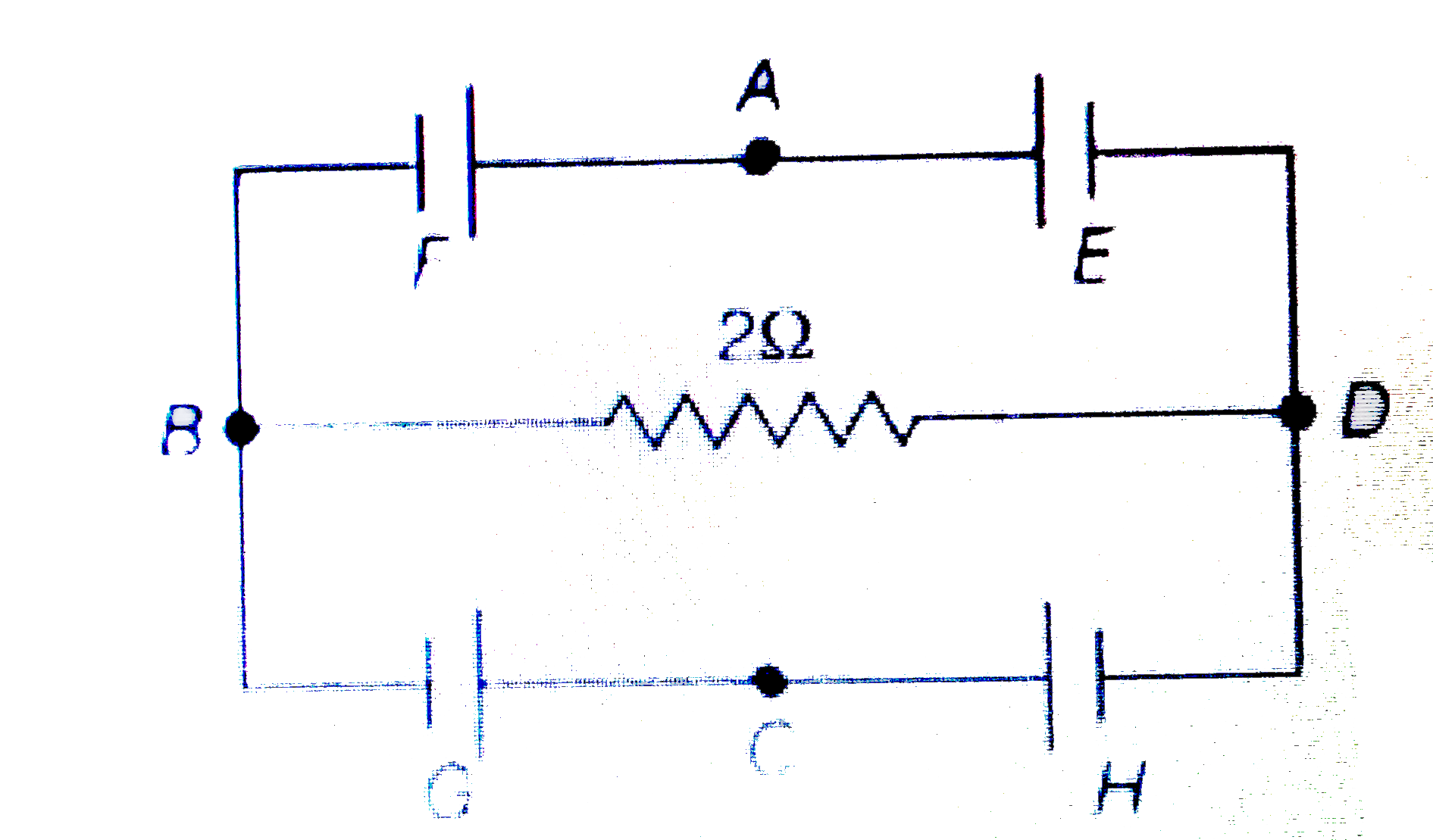
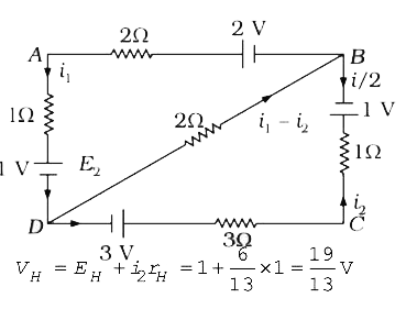
  3. In the circuit shown, E, F, G and H are cells of emf 2V, 1V, 3V and 1V...

    Text Solution

    |

  4. An infinite ladder is constructed with 1(Omega)and 2(Omega)resistor as...

    Text Solution

    |

  5. An electrical circuit is shown in figure. Calculate the potential diff...

    Text Solution

    |

  6. Find the emf (V) and internal resistance (R) of a single battery which...

    Text Solution

    |

  7. A thin uniform wire AB of length 1 m, an unknown resistance X, and a r...

    Text Solution

    |

  8. When two identical batteries of internal resistance 1Omega each are co...

    Text Solution

    |

  9. Two batteries of different emfs and different internal resistances are...

    Text Solution

    |

  10. A galvanometer gives full scale deflection with 0.006 A current. By co...

    Text Solution

    |

  11. In the following circuit, the current through the resistor R (=2Omega)...

    Text Solution

    |

  12. Two resistors 400Omega and 800Omega are connected in series with a 6 V...

    Text Solution

    |

  13. An electric bulb rated for 500 W at 100 V is used in a circuit having ...

    Text Solution

    |

  14. In the circuit shown in figure , each battery is 5 V and has an intern...

    Text Solution

    |

  15. The equivalent resistance between points A and B of the circuit given ...

    Text Solution

    |

  16. A 25W and 100W bulbs are joined in series and connected to the mains. ...

    Text Solution

    |

  17. When a steady current passes through a cylindrical conductor, is there...

    Text Solution

    |

  18. Determine True or False. Electrons in a conductor have no motion in th...

    Text Solution

    |

  19. The current - voltage graphs for a given metallic wire at two differen...

    Text Solution

    |

  20. We can use a rheostat as a potential divider.

    Text Solution

    |