Home
Class 12
PHYSICS
In the circuit shown below E-(1) = 4.0V,...

In the circuit shown below `E-(1) = 4.0V, R_(1) = 2Omega, E_(2) = 6.0V, R_(2)= 4 Omega` and `R-(3) = 2Omega`. The current `I_(1)` is

A

1.6A

B

1.8A

C

2.25A

D

1A

Text Solution

Verified by Experts

The correct Answer is:
B

For "loop" `(1) -2i_(1) -2(i_(1) - i_(2))+4`=0`rArr` `2i_(1) –i_(2)` = 2
For "loop"`(2) -4i_(2) -2(i_(1) - i_(2))+6`=0`rArr` `3i_(1) –i_(2)` = 3
After "solving" equation (1) and (11) we get `i_(1)` = 1.8 A and `i_(2)` = 1.6 A.
Promotional Banner

Topper's Solved these Questions

  • CURRENT ELECTRICITY

    VMC MODULES ENGLISH|Exercise PRACTICE EXERCISE-1|5 Videos
  • CURRENT ELECTRICITY

    VMC MODULES ENGLISH|Exercise PRACTICE EXERCISE-2|5 Videos
  • CURRENT ELECTRICITY

    VMC MODULES ENGLISH|Exercise IN-CHAPTER EXERCISE-F|10 Videos
  • CAPACITORS

    VMC MODULES ENGLISH|Exercise JEE Advance ( Archive ) LEVEL 48|1 Videos
  • DC CIRCUIT

    VMC MODULES ENGLISH|Exercise JEE ADVANCED ARCHIVE|68 Videos

Similar Questions

Explore conceptually related problems

In the circuit shown below E_(1) = 4.0 V, R_(1) = 2 Omega, E_(2) = 6.0 V, R_(2) = 4 Omega and R_(3) = 2 Omega . The current I_(1) is

In the following circuit , E_1 = 4V, R_1 = 2 Omega, E_2 = 6 V, R_2 = 2Omega, and R_3 = 4Omega. Find the currents i_1 and i_2

In the circuit shown, E_(1)= 7 V, E_(2) = 7 V, R_(1) = R_(2) = 1Omega and R_(3) = 3 Omega respectively. The current through the resistance R_(3)

In the circuit shown, E_(1)= 7 V, E_(2) = 7 V, R_(1) = R_(2) = 1Omega and R_(3) = 3 Omega respectively. The current through the resistance R_(3)

In the circuit shows in Fig E = 15 V , R_(1) = 1Omega , R_(2) = 1 Omega , R_(3) = 2Omega , and L = 1.5 H . The currents flowing through R_(1),R_(2) ,and R_(3) are i_(1),i_(2) , and i_(3) , respectively. Immediately after tuning switch S on,

In the circuit shows in Fig E = 15 V , R_(1) = 1Omega , R_(2) = 1 Omega , R_(3) = 2Omega , and L = 1.5 H . The currents flowing through R_(1),R_(2) ,and R_(3) are i_(1),i_(2) , and i_(3) , respectively. Immediately after connecting switch S ,

For the circuit shown E=50 V R_(1)=10 Omega , R_(2)= 20 Omega, R_(3) = 30 Omega L = 2.0 mH . The current through R_(1) and R_(2) are ________ . immediate after the switch is closed.

In the circuit shown below, E_(1)=17V,E_(2)=21V,R_(1)=2Omega,R_(2)=3Omega and R_(3)=5Omega . Using Kirchhoff.s laws, find the currents flowing through the resistors R_(1),R_(2) and R_(3) . (Internal resistance of each of the batteries is negligible.)

In the circuit shown in figure, R(1) = 1Omega, R_(2) = 2Omega, C_(1) = 1 muF, C_(2) = 2 muF and E = 6 V . Calculate charge on each capacitor in steady state

In the circuit shown in fig. R_(1) = 10 Omega, R_(2) = 5 Omega, C_(1) = 1 muF, C_(2) = 2muF, and E =6V. Calculate the charge on each capactor in the stedy state.

VMC MODULES ENGLISH-CURRENT ELECTRICITY-SOLVED EXAMPLES
  1. A rod of a certain metal is 1.0 m long and 0.6 cm in diameter. Its res...

    Text Solution

    |

  2. The equivalent resistance between points A and B of an infinite networ...

    Text Solution

    |

  3. A wire of resistance 0.5 ohm m^(-1) is bent into a circle of radius 1m...

    Text Solution

    |

  4. A battery of internal resistance 4 Omega is connected to he network of...

    Text Solution

    |

  5. A torch bulb rated 4.5 W, 1.5 V is connected as shown in Fig. 7.35. Th...

    Text Solution

    |

  6. In the below circuit, the battery E(1) has an emf of 12 V and zero int...

    Text Solution

    |

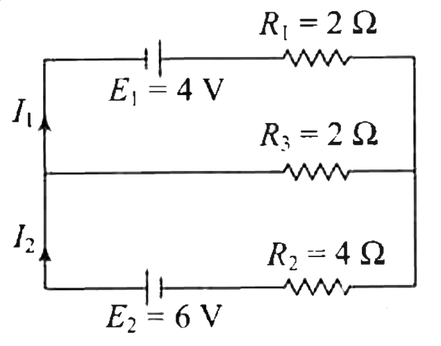
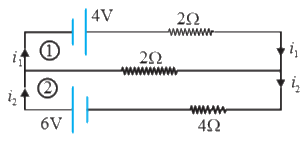
  7. In the circuit shown below E-(1) = 4.0V, R(1) = 2Omega, E(2) = 6.0V, R...

    Text Solution

    |

  8. Consider the circuit shown in the figure. The current I(3) is equal to

    Text Solution

    |

  9. A part of a circuit in steady state along with the currents flowing in...

    Text Solution

    |

  10. Three equal resistances, each of ROmega are connected as shown in figu...

    Text Solution

    |

  11. An electric bulb rated 220 V and 60 W is connected in series with anot...

    Text Solution

    |

  12. In an experiment to measure the internal resistance of a cell by a pot...

    Text Solution

    |

  13. A source of constant potential difference is connected across a conduc...

    Text Solution

    |

  14. Two electric bulbs rated P(1) and P(2) watt at V volt are connected in...

    Text Solution

    |

  15. In the given circuit, R(1) = 10Omega R(2) = 6Omega and E = 10V, then c...

    Text Solution

    |

  16. For the circuit shown, which option is incorrect

    Text Solution

    |

  17. An electric bulb rated for 500 W at 100 V is used in a circuit having ...

    Text Solution

    |

  18. If each resistance in the figure is of 9Omega then reading of ammeter ...

    Text Solution

    |

  19. A 100 W bulb B(1) and two 60W bulbs B(2) and B(3), are connected to a ...

    Text Solution

    |

  20. In the given circuit, with steady current, the potential difference ac...

    Text Solution

    |