


Similar Questions
Explore conceptually related problems
Recommended Questions
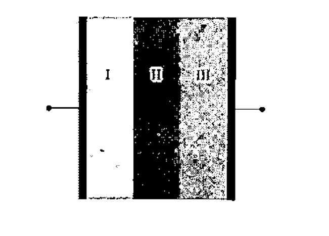
- Figure shows a capacitor having three layers of equal thickness and sa...
Text Solution
|
- The figure shows two identical parallel plate capacitors connected to ...
Text Solution
|
- Figure shows a capacitor having three layers between its plates. Layer...
Text Solution
|
- The plates of a capacitor are connected to a source of emf and the ene...
Text Solution
|
- A parallel plate capacitor with a dielectric slab with dielectric cons...
Text Solution
|
- The figure shows a capacitor having three dielectric layers parallel t...
Text Solution
|
- Figure shows a capacitor having three layers of equal thickness and sa...
Text Solution
|
- A parallel plate capacitor has two layers of dielectrons as shown in f...
Text Solution
|
- The separation between the two of an isolated charged parallel plate a...
Text Solution
|