


Similar Questions
Explore conceptually related problems
Recommended Questions
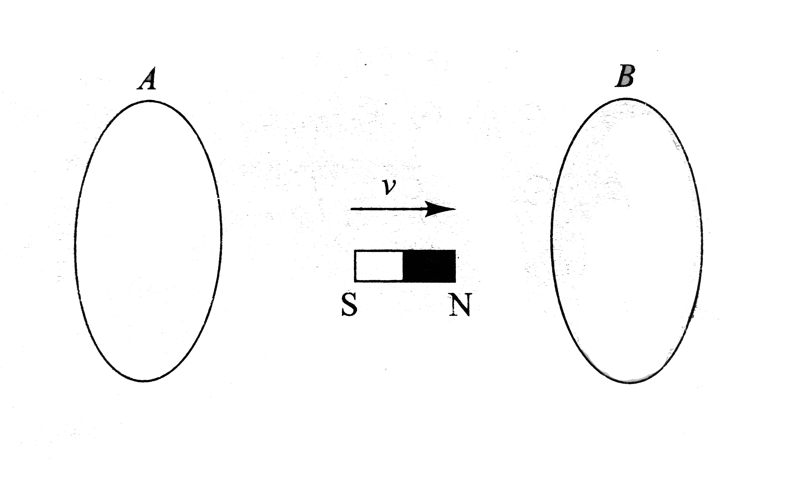
- A bar magnet is moved between two parallel circular loops A and B with...
Text Solution
|
- A circular loop of radius r moves with a constant velocity v in a regi...
Text Solution
|
- Loop A of radius rgtgtR moves toward loop B with a constant velocity V...
Text Solution
|
- A bar magnet is moved between two parallel circular loops A and B with...
Text Solution
|
- An electron moving with a velocity v along the positive x -axis approa...
Text Solution
|
- A bar magnet is moved towards a wire loop suspended as shown in fig .W...
Text Solution
|
- एक आयताकार लूप और एक वृतीय लूप को एक नियत वेग से एकसमान चुम्बकीय क्...
Text Solution
|
- A,B are two conducting circular loops with their planes parallel and a...
Text Solution
|
- R त्रिज्या का एक अर्द्धवृताकार लूप v वेग से समरूप अनुप्रस्थ चुम्बकीय क...
Text Solution
|