A
B
C
D
Text Solution
Verified by Experts
The correct Answer is:


Similar Questions
Explore conceptually related problems
Recommended Questions
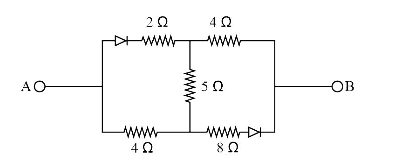
- The part of a circuit shown in the figure consists of two ideal diodes...
Text Solution
|
- Find the equivalent resistance of the circuits shown in figure between...
Text Solution
|
- Calculate the equivalent resistance of the circuit shown in figure bet...
Text Solution
|
- Each resistance of the circuit shown in figure is r. The equivalent re...
Text Solution
|
- In the circuit shown in figure , the diode is ideal The potential diff...
Text Solution
|
- The equivalent resistance between A and B for . the circuit shown in t...
Text Solution
|
- What is the resistance of the diode circuit between A and B. ( D1 and ...
Text Solution
|
- In the circuit shown in figure, the equivalent resistance between and ...
Text Solution
|
- The part of a circuit shown in the figure consists of two ideal diodes...
Text Solution
|