A
B
C
D
Text Solution
Verified by Experts
The correct Answer is:


Similar Questions
Explore conceptually related problems
Recommended Questions
- As shown in figure, the two parallel conducting rails, in a horizontal...
Text Solution
|
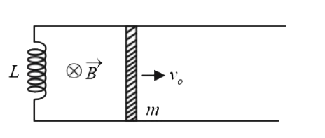
- Two parallel resistanceless rails are connected by an inductor of indu...
Text Solution
|
- Consider parallel conducting rails separated by a distance l. There ex...
Text Solution
|
- A conducting rod of length is moved at constant velocity v(0) on two p...
Text Solution
|
- A conducting rod PQ of mass m and length l is placed on two long paral...
Text Solution
|
- A conducting rod MN of mass m and length 'l' is placed on parallel smo...
Text Solution
|
- Two smooth horizontal parallel conducting rails are connected with a c...
Text Solution
|
- A rod AB of mass m and length l is placed on two smooth rails P and Q ...
Text Solution
|
- A pair of long, smooth, parallel, horizontal, conducting rails are joi...
Text Solution
|