Home
Class 12
PHYSICS
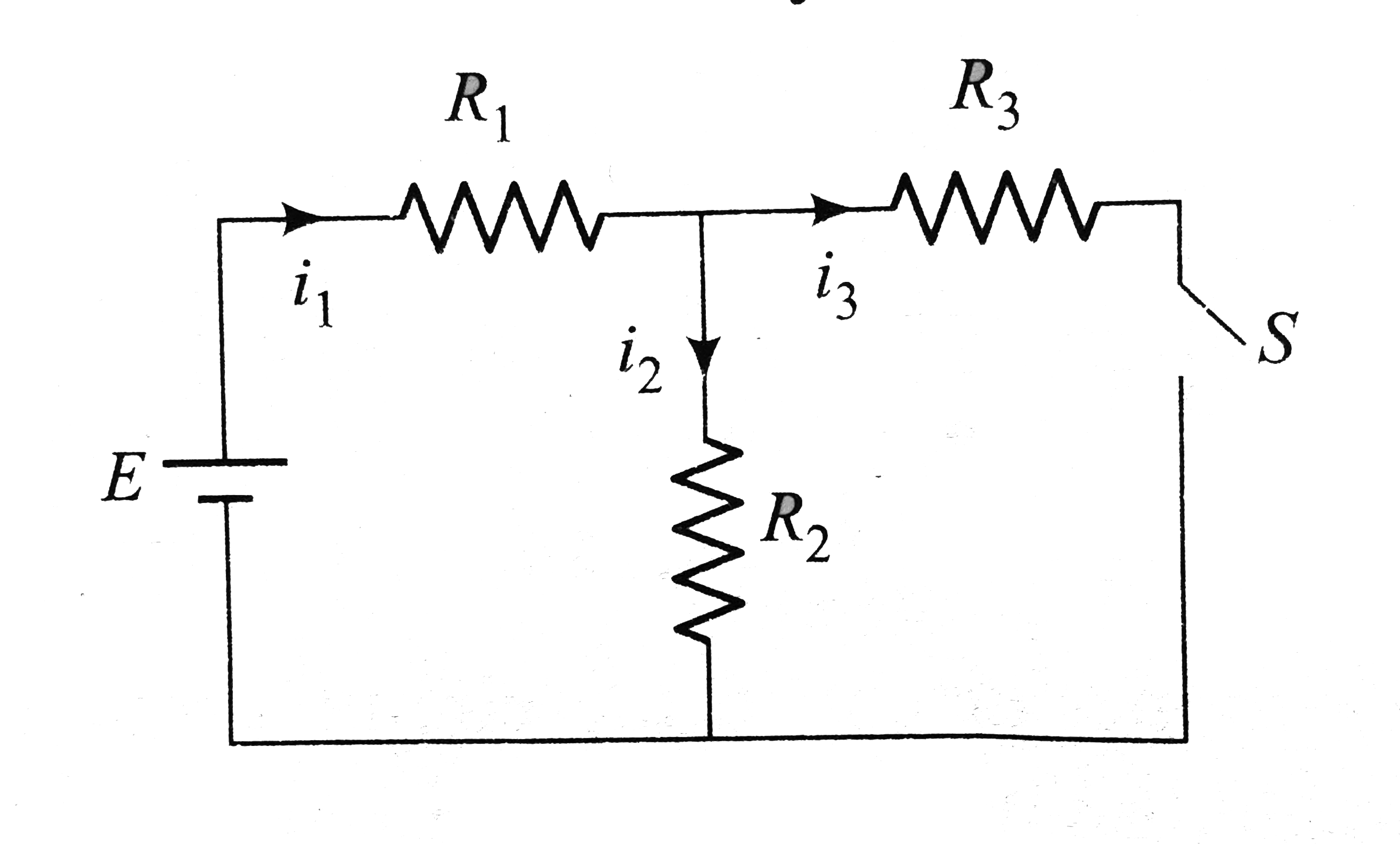
In the circuit shows in Fig E = 15 V, R(...

In the circuit shows in Fig `E = 15 V`, `R_(1) = 1Omega`, `R_(2) = 1 Omega`, `R_(3) = 2Omega`, and `L = 1.5 H`. The currents flowing through `R_(1),R_(2)`,and `R_(3)` are `i_(1),i_(2)`, and `i_(3)`, respectively.

Immediately after connecting switch `S`,

A

`i_(1) = 0A and (di_(3))/dt=0As^(-1)`

B

`i_(1) = 0A and (di_(3))/dtne0As^(-1)`

C

`i_(3)=0A`, and rate at which magnetic energy stored is not zero

D

None of these

Text Solution

Verified by Experts

The correct Answer is:
B
Promotional Banner

Similar Questions

Explore conceptually related problems

In the circuit shows in Fig E = 15 V , R_(1) = 1Omega , R_(2) = 1 Omega , R_(3) = 2Omega , and L = 1.5 H . The currents flowing through R_(1),R_(2) ,and R_(3) are i_(1),i_(2) , and i_(3) , respectively. Immediately after tuning switch S on,

In the circuit shown below E_(1) = 4.0 V, R_(1) = 2 Omega, E_(2) = 6.0 V, R_(2) = 4 Omega and R_(3) = 2 Omega . The current I_(1) is

For the circuit shown E=50 V R_(1)=10 Omega , R_(2)= 20 Omega, R_(3) = 30 Omega L = 2.0 mH . The current through R_(1) and R_(2) are ________ . immediate after the switch is closed.

In the circuit shown, E_(1)= 7 V, E_(2) = 7 V, R_(1) = R_(2) = 1Omega and R_(3) = 3 Omega respectively. The current through the resistance R_(3)

In the circuit shown, E_(1)= 7 V, E_(2) = 7 V, R_(1) = R_(2) = 1Omega and R_(3) = 3 Omega respectively. The current through the resistance R_(3)

In the following circuit , E_1 = 4V, R_1 = 2 Omega, E_2 = 6 V, R_2 = 2Omega, and R_3 = 4Omega. Find the currents i_1 and i_2

In the circuit shown in figure Current through R_(2) is zero if R_(4) = 2 Omega and R_(3) = 4 Omega In this case

In the circuit shown in fig. 5.265, E_1 = E_2 = E_3 = 2V and R_1 = R_2 = 4Omega. The current flowing between points A and B through battery E_2 is

In the circuit shown in fig. R_(1) = 10 Omega, R_(2) = 5 Omega, C_(1) = 1 muF, C_(2) = 2muF, and E =6V. Calculate the charge on each capactor in the stedy state.

In the circuit shown in figure, R(1) = 1Omega, R_(2) = 2Omega, C_(1) = 1 muF, C_(2) = 2 muF and E = 6 V . Calculate charge on each capacitor in steady state