A
B
C
D
Text Solution
Verified by Experts
The correct Answer is:


Similar Questions
Explore conceptually related problems
Recommended Questions
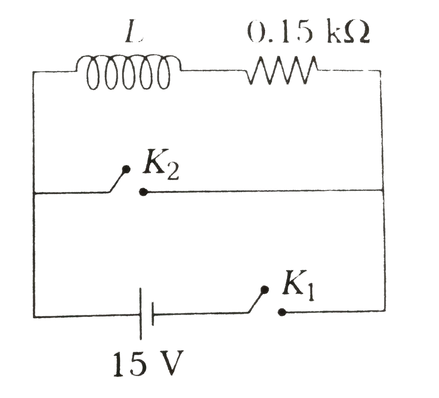
- An inductor (L = 0.03H) and a resistor (R = 0.15Omega) are connected i...
Text Solution
|
- An inductor (L =0.03 H) and a resistor (R = 0.15k(Omega)) are connecte...
Text Solution
|
- In the circuit shows in Fig. switch k(2) is open and switch k(1) is cl...
Text Solution
|
- A circuit containing capacitors C(1) and C(2) shown in Fig. is in the ...
Text Solution
|
- A capacitor of capacitance 3 mu F is first charged by connecting it ac...
Text Solution
|
- In the given circuit, calculate the ratio of currents through the batt...
Text Solution
|
- An inductor (L=0.03H) and a resistor (R=0.15kOmega) are connected in s...
Text Solution
|
- दिखाए गए परिपथ में एक प्रेरक (L=0.03 हेनरी) तथा एक प्रतिरोधक (R= 0.15k...
Text Solution
|
- Shown in the figure is a parallel R , L,C circuit with key K(1) closed...
Text Solution
|