Text Solution
Verified by Experts
The correct Answer is:


Similar Questions
Explore conceptually related problems
Recommended Questions
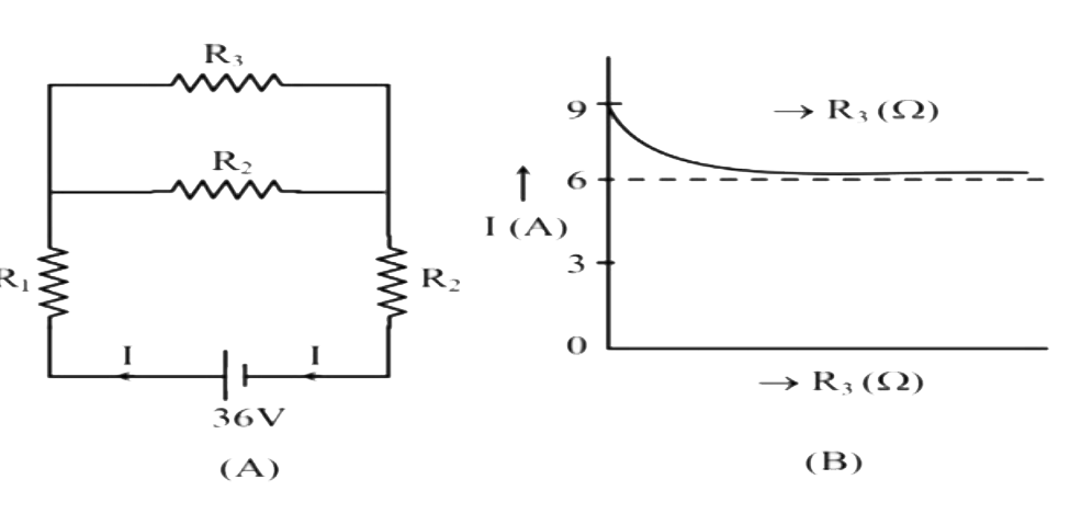
- In the circuit shown in the figure (A), R(3) is a variable resistance ...
Text Solution
|
- The circuit is shown in the following figure. The potential at points ...
Text Solution
|
- The potential difference in volt across the resistance R(3) in the cir...
Text Solution
|
- In the circuit shown in the given figure, the resistances R(1) and R(2...
Text Solution
|
- 5 resistances R(1), R(2),R(3),R(4),R(5) are joined as shown in the fig...
Text Solution
|
- In the situation shown, resistance R(1),R(2) and R(3) are in the ratio...
Text Solution
|
- In the circuit shown in the figure (A), R(3) is a variable resistance ...
Text Solution
|
- In the circuit shown, E(1)= 7 V, E(2) = 7 V, R(1) = R(2) = 1Omega and ...
Text Solution
|
- चित्र में प्रदर्शित परिपथ का तुल्य प्रतिरोध ज्ञात कीजिए तथा R(3) व R(4...
Text Solution
|