A
B
C
D
Text Solution
Verified by Experts
The correct Answer is:


Similar Questions
Explore conceptually related problems
Recommended Questions
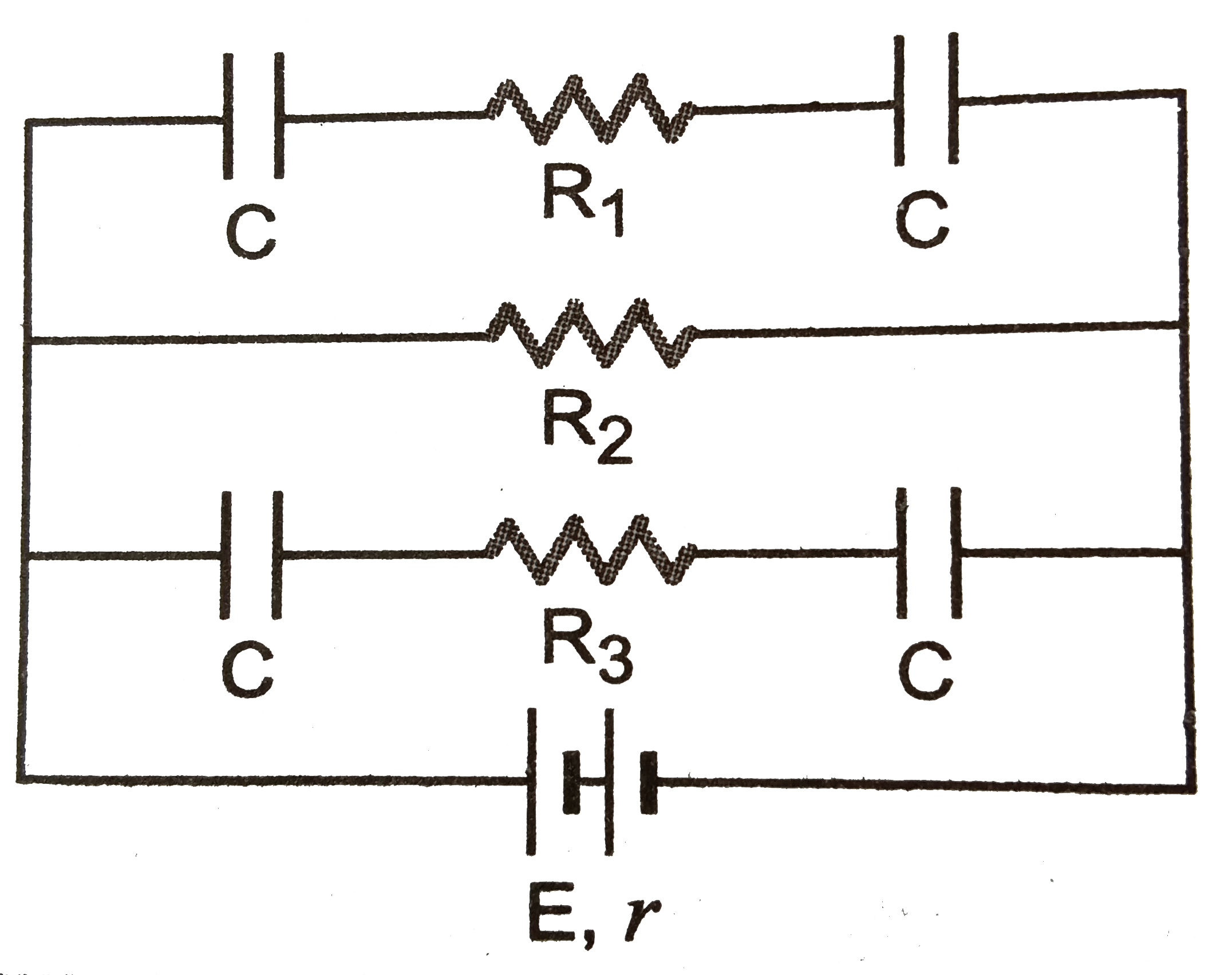
- In Fig, E =5 volt , r = 1 Omega, R(2) = 4 Omega, R(1) = R(3) = 1 Omeg...
Text Solution
|
- In the circuit shown in fig. R(1) = 10 Omega, R(2) = Omega, C(1) = 1 m...
Text Solution
|
- In Fig, E =5 volt , r = 1 Omega, R(2) = 4 Omega, R(1) = R(3) = 1 Omega...
Text Solution
|
- In the circuit R(1) = 4 Omega , R(2) = R(3) = 15 Omega R(4) = 30 Omega...
Text Solution
|
- Find the current flowing through the resistance R(1) of the circuit sh...
Text Solution
|
- In the circuit shown in the figure R(1) =3 Omega,R(2) = 2 Omega and R(...
Text Solution
|
- Determine the voltage drop across the resistance R(1) in the circuit g...
Text Solution
|
- संलगन चित्र मई प्रतिरोधक R(1)=15Omega,R(2)=10Omega, R(3)=30Omega,R(4)=...
Text Solution
|
- In the circuit shown in adjoining fig E =10V, R(1)=1 Omega R(2)=2 Omeg...
Text Solution
|