A
B
C
D
Text Solution
Verified by Experts
The correct Answer is:


Similar Questions
Explore conceptually related problems
Recommended Questions
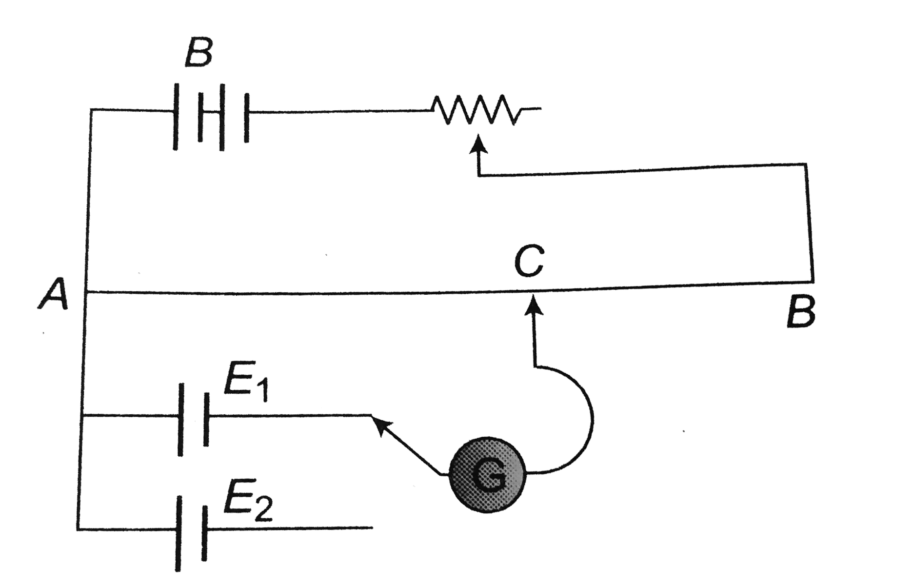
- The circuit shown here is used to compare the e.m.f. of the two cells ...
Text Solution
|
- The circuit shown here is used to compare the e.m.f. of the two cells ...
Text Solution
|
- Two cells of emf's E(1) and E(2) when placed in series produce null de...
Text Solution
|
- The balancing lengths for the cells of e.m.f. E(1) and E(2) are l(1) a...
Text Solution
|
- Two cells of e.m.f.'s E(1) and E(2) where E(1) gt E(2) , are connected...
Text Solution
|
- A potentiometer experiment is set up to compare the e.m.f.'s E(1) and ...
Text Solution
|
- Two cells of emf E(1) and E(2) are to be compared in a potentiometer...
Text Solution
|
- Two cells of emf E(1) and E(2) ( E(1) gt E(2)) are connected in series...
Text Solution
|
- Two batteries of emf E(1) and E(2)(E(2) gt E(1)) and internal resistan...
Text Solution
|