A
B
C
D
Text Solution
Verified by Experts
The correct Answer is:


Similar Questions
Explore conceptually related problems
Recommended Questions
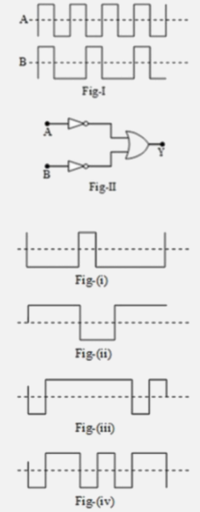
- Input waveforms A and B as shown in Fig-l are applied to the combinati...
Text Solution
|
- In Fig., circuit of a logic gate and input waveform is shown. (i) Name...
Text Solution
|
- Draw and explain the output waveform across the load resistor R, if th...
Text Solution
|
- The following Fig. shows the input waveforms (A,B) and the output wave...
Text Solution
|
- The Fig shown input waveforms A and B to a logic gate. Draw the output...
Text Solution
|
- The logic circuit shown belows has the input waveforms 'A' and 'B' as ...
Text Solution
|
- The logic circuit shown below has the input waveform 'A' and 'B' as sh...
Text Solution
|
- Two input waveforms A and B shown in fig (a) are applied to an AND gat...
Text Solution
|
- The logic circuit shown below has the inputs waveforms A and B as show...
Text Solution
|