A
B
C
D
Text Solution
Verified by Experts
The correct Answer is:


Similar Questions
Explore conceptually related problems
Recommended Questions
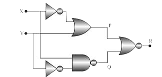
- Figure gives a system of logic gates. From the study of truth table it...
Text Solution
|
- Figure gives a system of logic gates. From the study of truth table it...
Text Solution
|
- In Fig., circuit of a logic gate and input waveform is shown. (i) Name...
Text Solution
|
- The Fig shown input waveforms A and B to a logic gate. Draw the output...
Text Solution
|
- चित्र में एक लॉजिक गेट का संकेत चित्र दिया गया है । (i) लॉजिक गेट का...
Text Solution
|
- OR गेट के लिए सत्यता सारणी लॉजिक प्रतीक , बूलियन व्यंजक तथा सत्यता सा...
Text Solution
|
- OR गेट के लिए सत्यता सारणी लॉजिक प्रतीक , बूलियन व्यंजक तथा सत्यता सा...
Text Solution
|
- The truth table of a logic gate is a table
Text Solution
|
- The figure gives a system of logic gates. From the study of the truth ...
Text Solution
|