A
B
C
D
Text Solution
Verified by Experts
The correct Answer is:


Similar Questions
Explore conceptually related problems
Recommended Questions
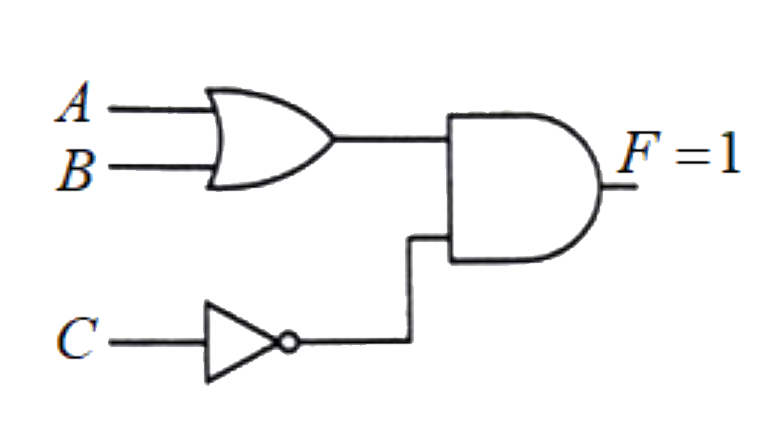
- For given logic diagram, outupt F = 1, then inputs are
Text Solution
|
- The diagram of a logic circuit is given below. The output F of the cir...
Text Solution
|
- The diagram shows a logic network. If the inputs L,M and N are all at ...
Text Solution
|
- The output of the given logic gate is 1 when inputs A,B and C are such...
Text Solution
|
- When the inputs of a two input logic gate are 0 and 0, the output is 1...
Text Solution
|
- चित्र में एक लॉजिक परिपथ में दो निवेशी A तथा B और एक निर्गत C दर्शाया ...
Text Solution
|
- For given logic diagram, outupt F = 1, then inputs are
Text Solution
|
- The diagram of a logic circuit is given below . The output F of the ci...
Text Solution
|
- The diagram of a logic circuit is given below . The output F of the ci...
Text Solution
|