A
B
C
D
Text Solution
Verified by Experts
The correct Answer is:


Similar Questions
Explore conceptually related problems
Recommended Questions
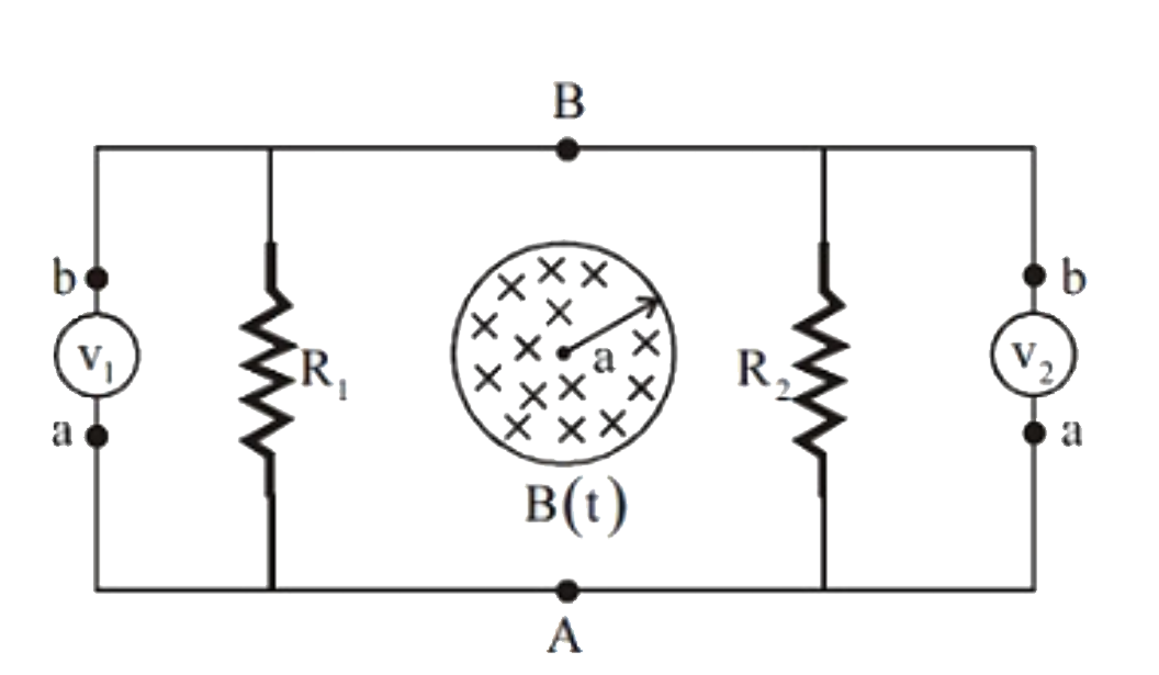
- The circuit shown in the figure consists of two resistances R(1) & R(2...
Text Solution
|
- A stationary circular loop of radius a is located in a magnetic field ...
Text Solution
|
- A time varying magnetic field is present in a cyclindrical region R as...
Text Solution
|
- Consider the circuit shown in the figure, the cell is ideal. The readi...
Text Solution
|
- In the circuit shown, an ideal cell of emf E is connected in series to...
Text Solution
|
- In the circuit shown in the figure, two resistors R(1) and R(2) have b...
Text Solution
|
- An uncharged capacitor C and a variable resistance R are connected to ...
Text Solution
|
- The resistance t R of a conductor varies with temperature t as shown ...
Text Solution
|
- The circuit shown in the figure consists of two resistances R(1) & R(2...
Text Solution
|