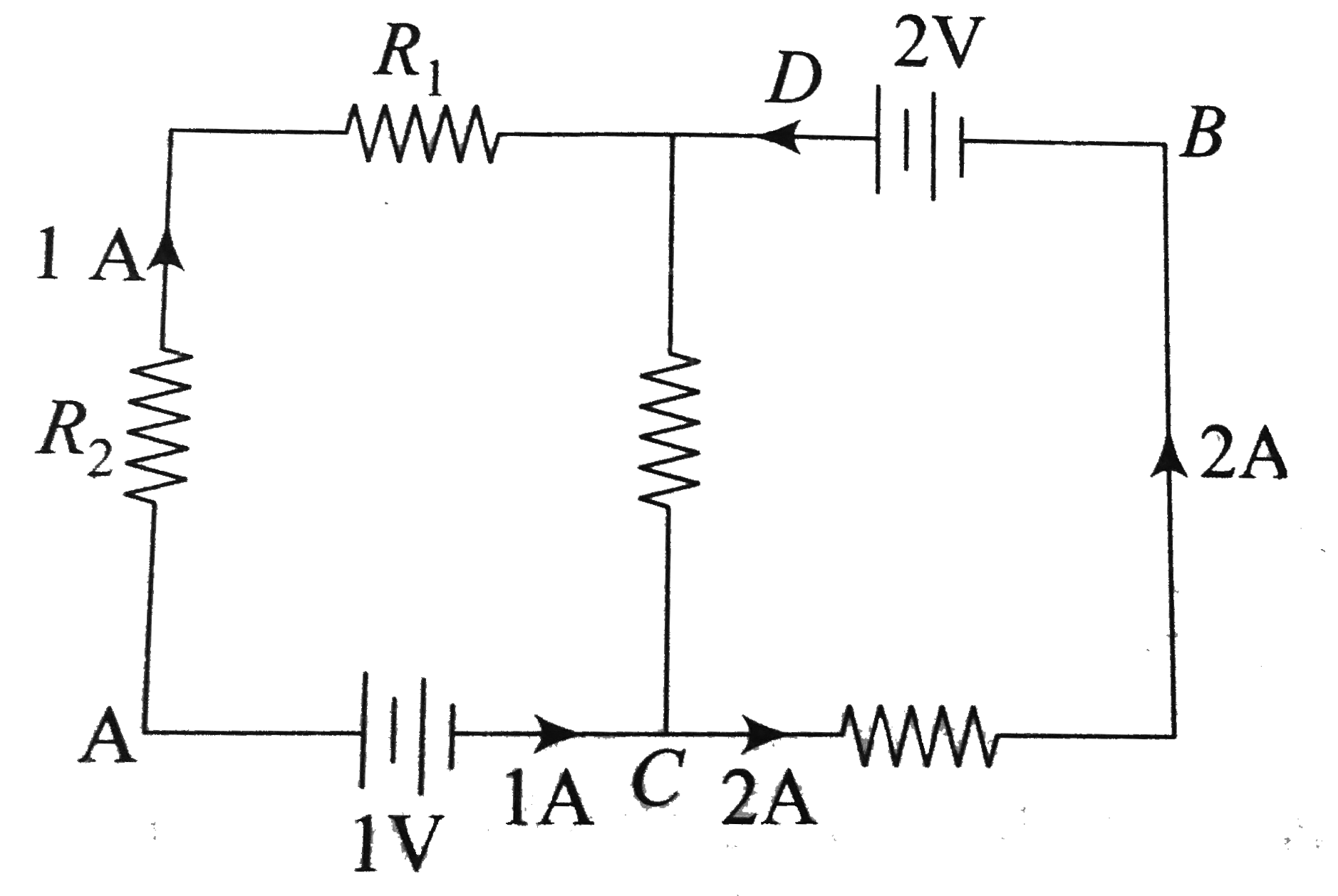
A
B
C
D
Text Solution
Verified by Experts
The correct Answer is:


Similar Questions
Explore conceptually related problems
Recommended Questions
- In the circuit shown in the figure, if potentail at point A is taken t...
Text Solution
|
- The potential difference between points A and B in the circuit shown i...
Text Solution
|
- In the circuit shown in figure potential difference between the points...
Text Solution
|
- In the circuit shown, the point B is earthed. The potential at the poi...
Text Solution
|
- In the circuit shown in the figure, if potentail at point A is taken t...
Text Solution
|
- In a circuit shown in the figure, what is potential of point A?
Text Solution
|
- In the given circuit the potential at point B is zero, the potential a...
Text Solution
|
- In the circuit it shown in the figure, the value of Resistance X, when...
Text Solution
|
- चित्र में दिखाये गये परिपथ में बिन्दु B और D के मध्य विभवान्तर शून्य ह...
Text Solution
|