A
B
C
D
Text Solution
AI Generated Solution
The correct Answer is:


Similar Questions
Explore conceptually related problems
Recommended Questions
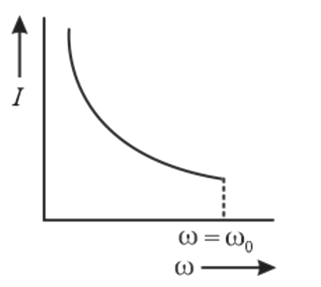
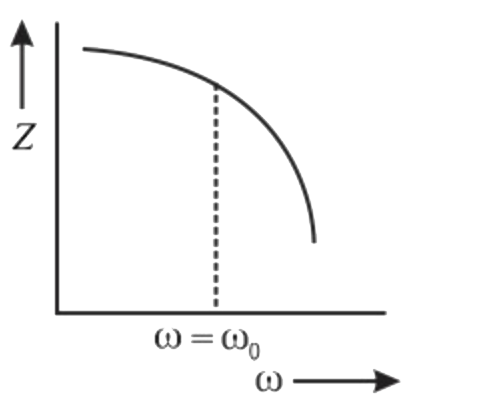
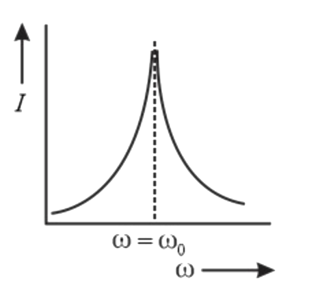
- The current graph for resonance in LC circuit is
Text Solution
|
- STATEMENT-1 : In series LC(AC) circuit, the current is infinite at res...
Text Solution
|
- Out of the following graphs, which graphs shows the correct relati...
Text Solution
|
- अनुनादी LC परिपथ की स्वाभाविक आवृत्ति का व्यंजक…………... है।
Text Solution
|
- Out of the following graphs, which grpahs shows the correct relation (...
Text Solution
|
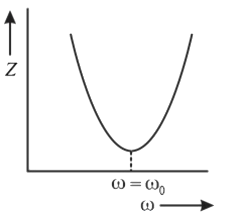
- The value of impedance in parallel LC circuit at resonance is (assumin...
Text Solution
|
- Out of the following graphs, which grpahs shows the correct relation (...
Text Solution
|
- परिपथ में अनुनादी आवृत्ति का सूत्र f=(1)/(2pi sqrt(LC)) है।
Text Solution
|
- सिद्ध कीजिए की प्रत्यावर्ती धारा से जुड़े LCR श्रेणी परिपथ की अनुनादी आ...
Text Solution
|