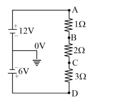
A
B
C
D
Text Solution
Verified by Experts
The correct Answer is:


Similar Questions
Explore conceptually related problems
Recommended Questions
- In the circuit diagram shown in Figure , the potentials of the points ...
Text Solution
|
- The potential difference between points A and B in the circuit shown i...
Text Solution
|
- In the circuit shown in figure potential difference between the points...
Text Solution
|
- In the circuit shown in the figure, if potentail at point A is taken t...
Text Solution
|
- In circuit shown in figure calculate the potential difference between ...
Text Solution
|
- What is the potential difference between the points A and B in the cir...
Text Solution
|
- In the circuit diagram shown in Figure , the potentials of the points ...
Text Solution
|
- In the circuit diagram shown in figure, the potentials of the points B...
Text Solution
|
- In the circuit , gives in the figure currents in different branches an...
Text Solution
|