A
B
C
D
Text Solution
Verified by Experts


Similar Questions
Explore conceptually related problems
Recommended Questions
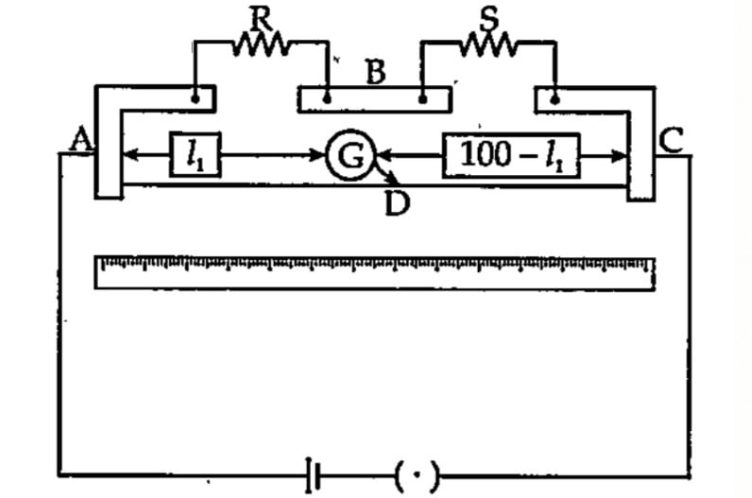
- In a meter bridge , as shown in the figure , the point D is a neutral ...
Text Solution
|
- In a meter bridge the point D is a neutral point (Fig. 2(EP).4).
Text Solution
|
- If the balancing point in a meter bridge from the left is 60 cm, compa...
Text Solution
|
- मीटर सेतु में सन्तुलन बिन्दु प्रायः मध्य भाग में क्यों प्राप्त करते है...
Text Solution
|
- चित्र में दिखाए अनुसार मीटर सेतु के प्रयोग में बिंदु A से 40 cm की दूर...
Text Solution
|
- दिए गए मीटर ब्रिज के चित्र में मीटर ब्रिज के तार में संतुलन बिन्दु कहा...
Text Solution
|
- Why is it generally preferred to obtain the balance point in the middl...
Text Solution
|
- In a meter bridge the point Dis a neutral point as shown in figure.
Text Solution
|
- The circuit of the meter bridge is shown in the figure. Zero deflectio...
Text Solution
|