

Home
Class 12
PHYSICS
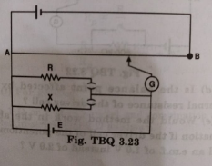
Figure shows potentionmeter circuit for ...

Figure shows potentionmeter circuit for comparison of two resistances. The balance point with a standard resistor R=10.0Ω is found to be 58.3 cm, while that with the unknown resistance X is 68.5 cm. Determine the value of X. What would you do if you failed to find a balance point with the given cell of emf E?

Promotional Banner

Similar Questions

Explore conceptually related problems

Figure shows a potentiometer circuit for comparison of two resistances. The balance point with a standard resistor R = 10 Omega is found to be 58.3 cm, while that with the unknown resistance x is 68.5 cm. determine the value of X.

Figure 3.34 shows a potentiometer circuit for comparison of two resistances. The balance point with a standard resistor R = 10.0 Omega is found to be 58.3 cm, while that with the unknown resistance X is 68.5 cm. Determine the value of X. What might you do if you failed to find a balance point with the given cell of emf epsilon ? :

Figure shows a potentiometer circuit for comparison of two resistances. The balance point with a standard resistor R = 10 Omega is found to be 58.3 cm, while that with the unknown resistance x is 68.5 cm. What would you do, if you failed to find a balance point with the given cell E?

A potentiometer wire of length 1 m has a resistance 10 ohm. It is connected to 6 V battery in series with a resistance of 5 ohm. Determine the emf of the primary cell which gives a balance point at 40 cm.

In a metre bridge [Fig. 3.27], the balance point is found to be at 39.5 cm from the end A, when the resistor R is of 12.5 Omega . Determine the balance point of the bridge above if R and S are interchanged. :

Figure 3.35 shows a 2.0 V potentiometer used for the determination of internal resistance of a 1.5 V cell. The balance point of the cell in open circuit is 76.3 cm. When a resistor of 9.5 Omega is used in the external circuit of the cell, the balance point shifts to 64.8 cm length of the potentiometer wire. Determine the internal resistance of the cell. :

In a metre bridge [Fig. 3.27], the balance point is found to be at 39.5 cm from the end A, when the resistor Y is of 12.5 Omega Determine the resistance of X. Why are the connections between resistors in a Wheatstone or meter bridge made of thick copper strips?:

Figure 3.33 shows a potentiometer with a cell of 2.0 V and internal resistance 0.40 Omega maintaining a potential drop across the resistor wire AB. A standard cell which maintains a constant emf of 1.02 V (for very moderate currents upto a few mA) gives a balance point at 67.3 cm length of the wire. To ensure very low currents drawn from the standard cell, a very high resistance of 600 k Omega is put in series with it, which is shorted close to the balance point. The standard cell is then replaced by a cell of unknown emf epsilon and the balance point found similarly, turns out to be at 82.3 cm length of the wire. Would the circuit work well for determining an extremely small emf, say of the order of a few mV (such as the typical emf of a thermo-couple)? If not, how will you modify the circuit?:

Figure 3.33 shows a potentiometer with a cell of 2.0 V and internal resistance 0.40 Omega maintaining a potential drop across the resistor wire AB. A standard cell which maintains a constant emf of 1.02 V (for very moderate currents upto a few mA) gives a balance point at 67.3 cm length of the wire. To ensure very low currents drawn from the standard cell, a very high resistance of 600 k Omega is put in series with it, which is shorted close to the balance point. The standard cell is then replaced by a cell of unknown emf epsilon and the balance point found similarly, turns out to be at 82.3 cm length of the wire. Is the balance point affected by the internal resistance of the driver cell?: