


Similar Questions
Explore conceptually related problems
Recommended Questions
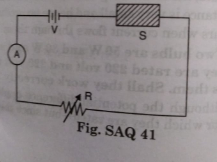
- The diagram shows a piece of pure semiconductor S, in series with a va...
Text Solution
|
- Figure shows a piece of semiconductor (pure one) S in series with a va...
Text Solution
|
- The diagram Fig.12 shown a piece of pure semiconductor S in series wit...
Text Solution
|
- A battery of emf 2 V and internal resistance r is connected in series ...
Text Solution
|
- ताप बढ़ने से अर्धचालक की चालकता घटती है।
Text Solution
|
- …………… अर्द्धचालको से बना ऐसा प्रतिरोधक होता है , जिसका प्रतिरोध ता...
Text Solution
|
- A conductor in series with an ammeter and a semiconductor in series wi...
Text Solution
|
- A semiconductor -resistor is connected in parallel with a variable res...
Text Solution
|
- चित्र मे एक अर्ध्द चालक चिप S एक परिवर्ती प्रतिरोध R तथा नियत वोल...
Text Solution
|