


Similar Questions
Explore conceptually related problems
Recommended Questions
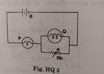
- The circuit shown in the diagram contains battery B, a rheostat Rh.and...
Text Solution
|
- The resistance of the rheostat shown in figure is 30(Omega). Neglectin...
Text Solution
|
- The circuit shownin Fig. 7.33 contains a battery , a rheostat , and tw...
Text Solution
|
- A circuit consists of three identical lamps connected to a battery as ...
Text Solution
|
- A circuit consists of three identical lamps connected to a battery as ...
Text Solution
|
- Schematic of a rheostat is shown in the figure. Connect a battery to i...
Text Solution
|
- कथन- 1 : यदि लैम्प की धारा 20% बढ़ाते है, लैम्प की चमक 40% बढ़ जाती है। ...
Text Solution
|
- प्रककथन : निम्न परिपथ में यदि लैम्प B या C फ्यूज हो जाता है, तब लैम्प ...
Text Solution
|
- An electric lamp of resistance 2 Omega and a conductor of resistance 4...
Text Solution
|