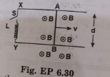
Find the current in the sliding rod AB (resitance = R) for the arrangement shown in Fig.EP.6.30. `vecB` is constant and is out of the paper. Parallel wires have no resistance `vecv` is constant. Switch S is closed at time t=0
Find the current in the sliding rod AB (resitance = R) for the arrangement shown in Fig.EP.6.30. `vecB` is constant and is out of the paper. Parallel wires have no resistance `vecv` is constant. Switch S is closed at time t=0


Similar Questions
Explore conceptually related problems
Find the current in the wire for the configuration shown in Fig. EP 6.19. Wire PQ has negligible resistance. B is the magnetic field is coming out of the paper theta is a fixed angle made by PQ travelling smoothly over two conducting paralel wire separated by a distance d.
Five long wires A, B, C, D and E, each carrying current I are arranged to form edges of a pentagonal prism as shown in Fig. EP 4.29. Each carries current out of the plane of paper. What will be magnetic induction at a point on the axis O? Axis is at a distance R from each wire.
A magnetic filed vecB=B_0 sin"(omega t)hatk covers a large region where a wire AB slides smoothly over two parallel conductors separated by a distance d (Fig. EP 6.22). The wires are in the x-y plane. The wire AB (of length d) has resistance R and parallel wires have negligible resistance. If AB is moving with velocity v, what is the current in the circuit? what is the force needed to keep the wire moving at constant velocity?
Figure shows a conducting rod PQ in contact with metal rails RP and SQ, which are 0.25 m apart in a uniform magnetic field of flux density 0.4T acting perpendicular to the plane of the paper. Ends R and S are connected through a 5 Omega resistance. What is the emf when the rod moves to the right with a velocity of 5ms^(-1) ? What is the magnitude and direction of the current through the 5 Omega resistance? If the rod PQ moves to the left with the same speed, what will be the new current and its direction?
A metal bar AB can slide on two parallel thick metallic rails separated by a distance l. A resistance R and an inductance L are connected to the rails as shown in the figure. A long straight wire carrying a constant current I_(0) is placed in the plane of the rails and perpendicular to them as shown. The bar AB is held at rest at a distance x_(0) from the long wire. At t=0, it is made to slide on the rails away from wire. Answer the following questions. Find a relation among i, (di)/(dt) and (d phi)/(dt) , where i is the current in the circuit and phi is the flux of the megnetic field due to the long wire through the circuit.
A multirange voltmeter can be constructed by using a galvanometer circuit as shown in Fig. EP 4.21. We want to construct a voltmeter that can measure 2V, 20V and 200 V using a galvanometer of resistance 10 Omega and that produces maximum deflection for current of 1 mA. find R_1 , R_2 and R_3 that have to be used.
Figure shows a potentiometer with a cell of 2.0 V and internal resistance 0.40 Omega maintaining a potential drop across the resistor wire AB. A standard cell which maintains a constant emf of 1.02 V (for very moderate currents upto a few mA) gives a balance point at 67.3 cm length of the wire. To ensure very low currents drawn from the standard cell, a very high resistance of 600 k Omega is put in series with it, which is shorted close to the balance point. The standard cell is then replaced by a cell of unknown emf epsilon and the balance point found similarly, turns out to be at 82.3 cm length of the wire. What purpose does the high resistance of 600 kOmega have? :
Figure 3.33 shows a potentiometer with a cell of 2.0 V and internal resistance 0.40 Omega maintaining a potential drop across the resistor wire AB. A standard cell which maintains a constant emf of 1.02 V (for very moderate currents upto a few mA) gives a balance point at 67.3 cm length of the wire. To ensure very low currents drawn from the standard cell, a very high resistance of 600 k Omega is put in series with it, which is shorted close to the balance point. The standard cell is then replaced by a cell of unknown emf epsilon and the balance point found similarly, turns out to be at 82.3 cm length of the wire. Is the balance point affected by the internal resistance of the driver cell?:
Figure 3.33 shows a potentiometer with a cell of 2.0 V and internal resistance 0.40 Omega maintaining a potential drop across the resistor wire AB. A standard cell which maintains a constant emf of 1.02 V (for very moderate currents upto a few mA) gives a balance point at 67.3 cm length of the wire. To ensure very low currents drawn from the standard cell, a very high resistance of 600 k Omega is put in series with it, which is shorted close to the balance point. The standard cell is then replaced by a cell of unknown emf epsilon and the balance point found similarly, turns out to be at 82.3 cm length of the wire. Would the method work in the above situation if the driver cell of the potentiometer had an emf of 1.0V instead of 2.0V? :
Figure 3.33 shows a potentiometer with a cell of 2.0 V and internal resistance 0.40 Omega maintaining a potential drop across the resistor wire AB. A standard cell which maintains a constant emf of 1.02 V (for very moderate currents upto a few mA) gives a balance point at 67.3 cm length of the wire. To ensure very low currents drawn from the standard cell, a very high resistance of 600 k Omega is put in series with it, which is shorted close to the balance point. The standard cell is then replaced by a cell of unknown emf epsilon and the balance point found similarly, turns out to be at 82.3 cm length of the wire. Would the circuit work well for determining an extremely small emf, say of the order of a few mV (such as the typical emf of a thermo-couple)? If not, how will you modify the circuit?:
Recommended Questions
- Find the current in the sliding rod AB (resitance = R) for the arrange...
Text Solution
|
- In the circuit arrangement shown in figure, the switch S is closed at ...
Text Solution
|
- In the circuit shown, switch S is closed at time t = 0 . Find the curr...
Text Solution
|
- Find the current in the sliding rod AB (resistance = R) for the arrang...
Text Solution
|
- Find the current in the sliding rod AB (resistance = R) for the arrang...
Text Solution
|
- At t=0 , switch S is closed. Find time constant of the circuit and cur...
Text Solution
|
- In the circuit shown in figure switch S is closed at time t=0, which s...
Text Solution
|
- Find the current in the sliding rod AB (resistance = R) for the arrang...
Text Solution
|
- Find the current in the sliding rod AB (resistance = R) for the arrang...
Text Solution
|