


Similar Questions
Explore conceptually related problems
Recommended Questions
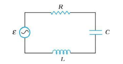
- Figure 7.21 shows a series LCR circuit connected to a variable frequen...
Text Solution
|
- Figure shows a series LCR circuit connected to a variable frequency 23...
Text Solution
|
- Figure here, shows a series L-C-R circuit connected to a variable freq...
Text Solution
|
- Figure shows a series LCR circuit connected to a variable frequency 23...
Text Solution
|
- Figure shows a series LCR circuit connected to a variable frequency 23...
Text Solution
|
- Figure shows a series LCR circuit connected to a variable frequency 23...
Text Solution
|
- A series LCR circuit is connected to a variable frequency 230 V source...
Text Solution
|
- Figure shows a series LCR circuit connected to a variable frequency 23...
Text Solution
|
- Figure shows a series LCR circuit connected to a variable frequency 23...
Text Solution
|