Home
Class 12
PHYSICS
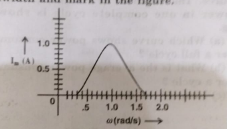
In series LCR circuit, the plot of Imax ...

In series LCR circuit, the plot of `I_max vs omega` is shown in Fig. EP 7.18 (a). Find the bandwidth and mark in the figure.

Promotional Banner

Similar Questions

Explore conceptually related problems

In the circuit shown in Fig. EP 14.40, find the value of R_c .

A series LCR circuit is connected to an a.c. source 220 V - 50 Hz as shown in fig. If the reading of the three voltemeters V_(1), V_(2), V_(3) are 65 V, 415 V and 204 V respectively. Calculate current in the circuit.

A series LCR circuit is connected to an a.c. source 220 V - 50 Hz as shown in fig. If the reading of the three voltmeters V_(1), V_(2), V_(3) are 65 V, 415 V and 204 V respectively. Calculate value of inductor L .

A series LCR circuit is connected to an a.c. source 220 V - 50 Hz as shown in fig. If the reading of the three voltemeters V_(1), V_(2), V_(3) are 65 V, 415 V and 204 V respectively R=100 ohm. Calculate value of C for same L required to produce resonance.

A series LCR circuit is connected to an a.c. source 220 V - 50 Hz as shown in fig. If the reading of the three voltemeters V_(1), V_(2), V_(3) are 65 V, 415 V and 204 V respectively. Calculate value of capacitor C.

Study the circuits (a) and (b) shown in Fig. EP 7.16 and answer the following questions. Under which conditions would the rms currents in the two circuits be the same?

A magnetic field in a certain region is given by bar B = B_0 cos omegathatk and a coil of radius a with resistanc R is placed i the XY-plane with its centre at the origin in the magnetic field as shown in the figure. Find the magnitude and direction of current at (a,0,0) at t = pi//2 omega

Study the circuits (a) and (b) shown in Fig. EP 7.16 and answer the following questions. Can the rms current in circuit (b) in larger than in (a)?

Figure shows a series LCR circuit connected to a variable frequency 230 V source. L = 5.0 H, C = 80 muF , R= 40 Omega . Obtain the impedance of the circuit and the amplitude of current at the resonating frequency. :

Figure 7.21 shows a series LCR circuit connected to a variable frequency 230 V source. L = 5.0 H, C = 80 muF , R= 40 Omega . Determine the source frequency which drives the circuit in resonance. :