Home
Class 12
PHYSICS
In Fig. EP 14.3, assuming the diodes to ...

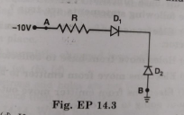
In Fig. EP 14.3, assuming the diodes to be ideal.

A

`D_1` is forward biased and `D_2` is reverse biased and hence current flows from A to B.

B

`D_2` is forward biased and `D_1` is reverse biased and hence no current flows from B to A and vice versa.

C

`D_1` and `D_2` are both forward biased and hence current flows from A to B.

D

`D_1` and `D_2` are both reverse biased and hence no current flow from A to B and vice versa.

Text Solution

Verified by Experts

Promotional Banner

Similar Questions

Explore conceptually related problems

In the circuit shown in Fig. EP. 14.7, if the diode forward voltage drop is 0.3 V, the voltage differnece between A and B is

In the circuit shown in Fig. EP 14.40, find the value of R_c .

What does the point P in Fig. EP 14.23 (a) represent for a diode?

In Fig. EP 14.2 V_0 is the potential barrier across a p-n junction when no battery is connected across the junction.

The following table provides the set of values, of V and I, obtained for a given diode. Assuming the characteristics to be nearly linear, over this range, calculate the forward and reverse bias resistance of the given diode.

Write the truth table for the circuit shown in Fig. EP 14.29. Name the gate that the circuit resembles.

If the resistance, R_1 is increased (Fig. EP. 14.25) how will the readings of the ammeter and voltmeter change?

In series LCR circuit, the plot of I_max vs omega is shown in Fig. EP 7.18 (a). Find the bandwidth and mark in the figure.

Consider a two slit interference arrangements (Fig. EP 10.18) such that the distance of the screen from the slits is half the distance between the slits. Obtain the value of D in terms of lambda such that the first minima on the screen falls at a distance D from the center O.