A
B
C
D
Text Solution
Verified by Experts


Similar Questions
Explore conceptually related problems
Recommended Questions
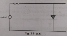
- The output of the given circuit in Fig. EP. 14.6.
Text Solution
|
- Find output y in the folowing circuit Fig. .
Text Solution
|
- The output of the given circuit in Fig.
Text Solution
|
- In the circuit Fig. the output y becomes zero for the inputs
Text Solution
|
- The output of the given circuit in Fig. .
Text Solution
|
- The output of the given circuit in Fig 1.53.
Text Solution
|
- चित्र में दिए गए स्नोजिक परिपथ का निर्गत X डोगा---
Text Solution
|
- The output of the given circuit in Fig.
Text Solution
|
- एक तार्किक परिपथ को चित्र में दर्शाया गया है। परिपथ से निर्गत F किससे ...
Text Solution
|