A
B
C
D
Text Solution
Verified by Experts


Similar Questions
Explore conceptually related problems
Recommended Questions
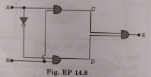
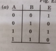
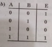
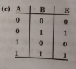
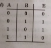
- Truth table for the given circuit (Fig. EP 14.8) is
Text Solution
|
- Write the truth table for the circuit given in Fig., consisting of NOR...
Text Solution
|
- Write the truth table for the circuit shown in Fig.
Text Solution
|
- Write the truth table for the circuit shown in Fig. Name the gate that...
Text Solution
|
- Truth table for the given circuit (Fig.)is
Text Solution
|
- The truth table for the circuit given in the fig. is:
Text Solution
|
- Truth table for the given circuit is
Text Solution
|
- Truth table for the given circuit is
Text Solution
|
- Write the truth table for the circuit given in Fig., consisting of NOR...
Text Solution
|