Home
Class 11
PHYSICS
A diode made forward biased by a two vol...


A diode made forward biased by a two volt battery however there is a drop of 0.5 V across the diode which is independent of current. Also a current greater then 10 mA produces large joule loss and damages diode. If diode is to be operated at 5 mA, the series resistance to be put is

A

`3 k Omega`

B

`300 k Omega`

C

`300 Omega`

D

`200 k Omega`

Text Solution

Verified by Experts

The correct Answer is:
C

`I=(V-V_(b))/(R)rArr510^(-2)=((2=0.5))/(R)rArrR=300 Omega`
Promotional Banner

Topper's Solved these Questions

  • SEMICONDUCTORS

    ALLEN |Exercise Part-3(Exercise-3)|27 Videos
  • SEMICONDUCTORS

    ALLEN |Exercise Part-3(Exercise-4)|50 Videos
  • SEMICONDUCTORS

    ALLEN |Exercise Part-3(Exercise-1)|84 Videos
  • PHYSICAL WORLD, UNITS AND DIMENSIONS & ERRORS IN MEASUREMENT

    ALLEN |Exercise EXERCISE-IV|7 Videos
  • WAVES AND OSCILLATIONS

    ALLEN |Exercise Part-1(Exercise-05)[B]|42 Videos

Similar Questions

Explore conceptually related problems

A P-N junction diode can withstand currents up to 10 mA . Under forward bias, The diode has a potential drop of 0.5 V across it which is assumed to be independent of current. The maximum voltage of the battery used to forward bias the diode when a resistance of 200 Omega is connected in series with it is

Keeping forward bias voltage from 0.6 V to 0.7 V in a p-n junction diode its current become 1 mA to 3mA. The dynamic resistance of diode is …….

Giving 2V to LED passes a 10 mA current. If you want to connect this diode to a 6V battery, then the value of resistance in series kept……

5 In a Zener regulated power supply a Zener diode with V_(Z) = 6.0 V is used for regulation. The load current is to be 4.0 mA and the unregulated input is 10.0 V. What should be the value of series resistor R_(S) ?

In a Zener regulated power supply a Zener diode with V_(Z)=6.0V is used for regulation. The load current is to be 4.0 mA and the unregulated input is 10.0V. What should be the value of series resistor R_(S) ?

When a 12V battery is connected across an unknown resistor, there is a current of 2.5 mA in the circuit. Find the value of the resistance of the resistor.

In a p-n junction diode, the current I can be expressed as I= I_(0) "exp" ((eV)/(2k_(B)T)-1) where I_(0) is called the reverse saturation current, V is the voltage across the diode and is positive for forward bias and negative for reverse bias, and I is the current through the diode, k_(B) is the Boltzmann constant (8.6 xx 10^(–5) eV//K) and T is the absolute temperature. If for a given diode I_(0) = 5 xx 10^(-12) A and T = 300 K, then (a) What will be the forward current at a forward voltage of 0.6 V? (b) What will be the increase in the current if the voltage across the diode is increased to 0.7 V? (c) What is the dynamic resistance? (d) What will be the current if reverse bias voltage changes from 1 V to 2 V?

In a p-n junction diode, the current I can be expressed as I=I_(0)"exp"((eV)/(2k_(B)T)-1) where I_(0) is called the reverse saturation current, V is the voltage across the diode and is positive for forward bias and negative for reverse bias, and I is the current through the diode, k_(B) is the Boltzmann constant (8.6xx10^(-5)eV//K) and T is the absolute temperature. If for a given diode I_(0)=5xx10^(-12) A and T = 300 K, then (a) What will be the forward current at a forward voltage of 0.6 V ? (b) What will be the increase in the current if the voltage across the diode is increased to 0.7 V ? (c ) What is the dynamic resistance? (d) What will be the current if reverse bias voltage changes from 1 V to 2 V ?

A light emitting diode (LED) has a voltage drop of 2 volt across it and passes a current of 10 mA when it operates with a 6 volt battery through a limiting register R. The value of R is ……

An experimental setup of verification of photoelectric effect is shown in the diagram. The voltage across the electrode is measured with the help of an ideal voltmetar, and which can be varied by moving jockey 'J' on the potentiometer wire. The battery used in potentiometer circuit is of 20 V and its internal resistance is 2omega . The resistance of 100 cm long potentiometer wire is 8 omega . The photo current is measured with the help of an ideal ammeter. Two plates of potassium oxide of area 50 cm^(2) at separation 0.5 mm are used in the vacuum tube. Photo current in the circuit is very small so we can treat potentiometer circuit an indepdent circuit. The wavelength of various colours is as follows : |{:("Light",underset("Violet")(1),underset("Blue")(2),underset("Green")(3),underset("Yellow")(4),underset("Orange")(5),underset("Red")(6)),(lambda "in" Årarr,4000-4500,4500-5000,5000-5500,5500-6000,6000-6500,6500-7000):}| When radiation falls on the cathode plate a current of 2muA is recorded in the ammeter. Assuming that the vecuum tube setup follows ohm's law, the equivalent resistance of vacuum tube operating in this case when jockey is at end P.

ALLEN -SEMICONDUCTORS-Part-3(Exercise-2)
  1. In sample of pure silicon 10^(13) "atom"//cm^(3) is mixed of phosphoru...

    Text Solution

    |

  2. Mobility of electron in N-type Ge is 5000 cm^(2)//"volt" sec and condu...

    Text Solution

    |

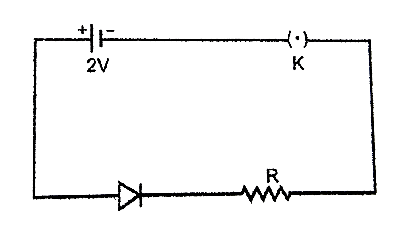
  3. A diode made forward biased by a two volt battery however there is a d...

    Text Solution

    |

  4. Forbidden energy gap of Ge is 0.75eV, maximum wave length of incident ...

    Text Solution

    |

  5. In the figure, the input is across the terminals A and C and the o...

    Text Solution

    |

  6. An oscillator is nothing but an amplifier with

    Text Solution

    |

  7. In the following common emitter configuration an NPN transistor with c...

    Text Solution

    |

  8. In the given transistor circuit, the base current is 35 muA. The value...

    Text Solution

    |

  9. In the cuircuit shown here the transistor used has a current gain beta...

    Text Solution

    |

  10. Choose the only false statement from the following.

    Text Solution

    |

  11. What will be conductance of pure silicon crystal at 300 K Temp. If ele...

    Text Solution

    |

  12. The output of the given logic gate is 1 when inputs A,B and C are such...

    Text Solution

    |

  13. The arrangement shown in figure performs the logic function of a/an….g...

    Text Solution

    |

  14. You are given two circuits as shown in following figure. The logic ope...

    Text Solution

    |

  15. Which of the following Boolean expression is not correct :-

    Text Solution

    |

  16. Which of the following relation is valid in Boolean algebra :-

    Text Solution

    |

  17. Given below are four logic tage symboles. Those for OR, NOR and NAND a...

    Text Solution

    |

  18. The output Y of the combination of gates shown in equal to :-

    Text Solution

    |

  19. Which of the following relation is valid in Boolean algebra :-

    Text Solution

    |

  20. The diagram of a logic circuit is given below. The output F of the cir...

    Text Solution

    |