Home
Class 11
PHYSICS
a p -n juction (D) shown in the figure c...

a p -n juction (D) shown in the figure can act an a rectifier An alternatting current source (V) is connected in the circuit

The corrent (I ) in the resistor® can be shown by :

A

B

C

D

Text Solution

Verified by Experts

The correct Answer is:
A
Promotional Banner

Topper's Solved these Questions

  • SEMICONDUCTORS

    ALLEN |Exercise Part-3(Exercise-3)|27 Videos
  • PHYSICAL WORLD, UNITS AND DIMENSIONS & ERRORS IN MEASUREMENT

    ALLEN |Exercise EXERCISE-IV|7 Videos
  • WAVES AND OSCILLATIONS

    ALLEN |Exercise Part-1(Exercise-05)[B]|42 Videos

Similar Questions

Explore conceptually related problems

A 3 volt battery with negligible internal resistance is connected in a circuit as shown in the figure. The current I in the circuit will be :

In an electric circuit, how can the battery having 12 V be shown symbolically ?

In an electric circuit, how can the battery having 12 V be shown symbolically?

Study the circuits (a) and (b) shown in figure and answer the following questions. (a) Under which conditions would the rms currents in the two circuits be the same ? (b) Can the rms current in circuit (b) be larger than that in (a) ?

As shown in the figure, P and Q are two coaxial conducting loops separated by some distance. When the switch S is closed, a clockwise current I_P flows in loop P (As seen by E) and an induced current I_Q flows in loop Q. In which direction this induced current I_Q will flow as seen by E ?

Figure shows a series LCR circuit connected to a variable frequency 230 V source. L = 5.0 H, C = 80muF, R = 40 Omega . (a) Determine the source frequency which drives the circuit in resonance. (b) Obtain the impedance of the circuit and the amplitude of current at the resonating frequency. (c) Determine the rms potential drops across the three elements of the circuit. Show that the potential drop across the LC combination is zero at the resonating frequency.

Six similar bulbs are connected as shown in the figure with a DC source of emf E, and zero internal resistance. The ratio of power consumption by the bulbs when (i) all are glowing and (ii) in the situation when two from section A and one from section B are glowing, will be : (a) 2: 1 (b) 4 : 9 (c) 9 : 4 (d) 1 : 2

Three resistors, an ideal cell are connected as shown in figure. The switch is initially open. When we close the switch, the current in the resistor R_(2) will.

A group of N cells whose emf varies directly with the internal resistance as per the equation E_(N)=1.5r_(N ) are connected as shown in the figure. The current in the circuit is

A resistor of 200 Omega and a capacitor of 15.0 muF are connected in series to a 220 V, 50 Hz ac source. (a) Calculate the current in the circuit, (b) Calculate the voltage (rms) across the resistor and the capacitor. Is the algebraic sum of these voltages more than the source voltage? If yes, resolve the paradox.

ALLEN -SEMICONDUCTORS-Part-3(Exercise-4)
  1. A working transitor with its three legs marked P, Q and R is tested us...

    Text Solution

    |

  2. In the circuit below, A and B represents two inputs and C represents t...

    Text Solution

    |

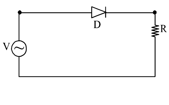
  3. a p -n juction (D) shown in the figure can act an a rectifier An alter...

    Text Solution

    |

  4. The logic circuit shown below has the input waveform 'A' and 'B' as sh...

    Text Solution

    |

  5. The combination of gates shown below yields :-

    Text Solution

    |

  6. The question has statement - 1 and statement - 2 Of the four choices ...

    Text Solution

    |

  7. If the output of the OR gate is connected to both inputs of the NAND g...

    Text Solution

    |

  8. Which of the following four alternatives is not correct, We need modul...

    Text Solution

    |

  9. Truth table for system of four NAND gates as shown in figure is : .

    Text Solution

    |

  10. A diode detector is used to detect an amplitude modulated wave of 60% ...

    Text Solution

    |

  11. The I- V characteristic of on LED is

    Text Solution

    |

  12. The forward biased diode connection is

    Text Solution

    |

  13. A single of 5 kHz frequency is amplitude modulated on a carrier wave o...

    Text Solution

    |

  14. In an unbiased p-n junction electrons diffuse from n-region to p-regio...

    Text Solution

    |

  15. A 2V battery is connected across AB as shown in the figure. The value ...

    Text Solution

    |

  16. The value of the resistor, R(S), needed in the dc voltage regulator ci...

    Text Solution

    |

  17. Choose the correct statement.

    Text Solution

    |

  18. For common emitter configuration, if alpha and beta have their usual m...

    Text Solution

    |

  19. if a,b,c,dare inputs to a gate and x is its output , then as per the f...

    Text Solution

    |

  20. The temperature dependence of resistances of Cu and undoped Si in the ...

    Text Solution

    |