Home
Class 12
PHYSICS
In the figure shown a converging lens an...

In the figure shown a converging lens and a diverging lens of focal lengths 20cm and -5cm respectively are separated by a distance such that a paralle beam of light of intensity 100 `watt//m^(2)` incident on the converging lens comes out as parallel beam from the diverging lens. Find the intensity of the outgoing beam in `watt//m^(2)`

A

`400 watt//m^(2)`

B

`1200 watt//m^(2)`

C

`1600 watt//m^(2)`

D

`800 watt//m^(2)`

Text Solution

Verified by Experts

The correct Answer is:
C


`(I)_("out")=(100(pir_(0)^(2)))/(pi((r_(0))/(4))^(2))=1600 W//m^(2)`
Promotional Banner

Topper's Solved these Questions

  • TEST PAPERS

    ALLEN |Exercise PAPER 3|92 Videos
  • TEST PAPERS

    ALLEN |Exercise Part-1 Physics|15 Videos
  • TEST PAPERS

    ALLEN |Exercise MATHS|1 Videos
  • TEST PAPER 4

    ALLEN |Exercise PHYSICS|45 Videos
  • UNIT & DIMENSIONS, BASIC MATHS AND VECTOR

    ALLEN |Exercise Exercise (J-A)|7 Videos

Similar Questions

Explore conceptually related problems

A converging lens of focal length f_(1) is placed in front of and coaxially with a convex mirror of focal length f_(2) . Their separation is d. A parallel beam of light incident on the lens returns as a parallel beam from the arrangement, Then,

As shown in figure, a plano-convex lens of focal length 20 cm is silvered at its plane surface and it is made reflecting, then find new focal length of system.

A diverging lens with magnitude of focal length 25 cm is placed at a distance of 15 cm from a converging lens of magnitude of focal length 20 cm. A beam of parallel light falls on the diverging lens. The final image formed is ......

Consider a 'beam expander' which consists of two converging lenses of focal length 40 cm and 100 cm having a common optical axis. A laser beam of diameter 4 mm is incident on the 40 cm focal length lens. Then what is the diameter of the final beam (see figure)

In the figure shown L is converging lens of focal length 10 cm and M is a concave mirror of radius of curvature 20 cm . A point object O is placed in front of the lens at a distance 15 cm . AB and CD are optical axes of the lens mirror respectively. Find the coordinates of the final image formed by this system taking O as origin. The distance between CD & AB is 1mm.

A diverging lens of focal length 10cm is placed 10cm in front of a plane mirror as shown in Fig. Light from a very far away source falls on the lens. What is the distance of final image?

What is the focal length of a convex lens of focal length 30cm in contact with a concave lens of focal length 20cm? Is the system a converging or a diverging lens? Ignore thickness of the lenses.

A converging lens of focal length 20 cm and diameter 5 cm is cut along the line AB . The part of the lens shown shaded in the diagram is now used to form an image of a point P placed 30 cm away from it on the line XY which is perpendicular to the plane of the lens. The image of P will be formed.

A linear aperture whose width is 0.02 em is placed immediately in front of a lens of focal length 60 cm. The aperture is illuminated normally by a parallel beam of wavelength 5 xx 10^(-5) cm . The distance of the first dark band of the differation pattern from the centre of the screen is .......

A compound microscope consists of an objective lens of focal length 2.0 cm and an eyepiece of focal length 6.25 cm separated by a distance of 15cm. How far from the objective should an object be placed in order to obtain the final image at (a) the least distance of distinct vision (25cm), and (b) at infinity? What is the magnifying power of the microscope in each case?

ALLEN -TEST PAPERS-PAPER 2
  1. The dispersive powers of two materials are 0.30 & 0.28. They are used ...

    Text Solution

    |

  2. Assume standard notations used for dispersion and deviation is a prism...

    Text Solution

    |

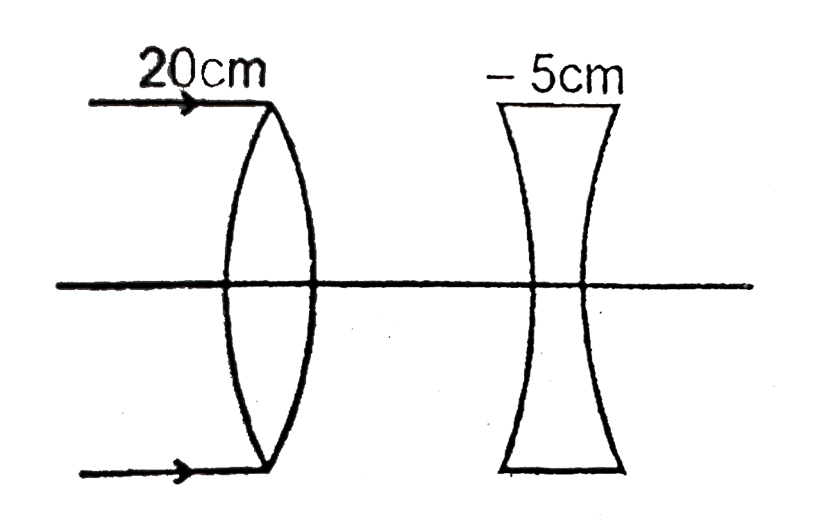
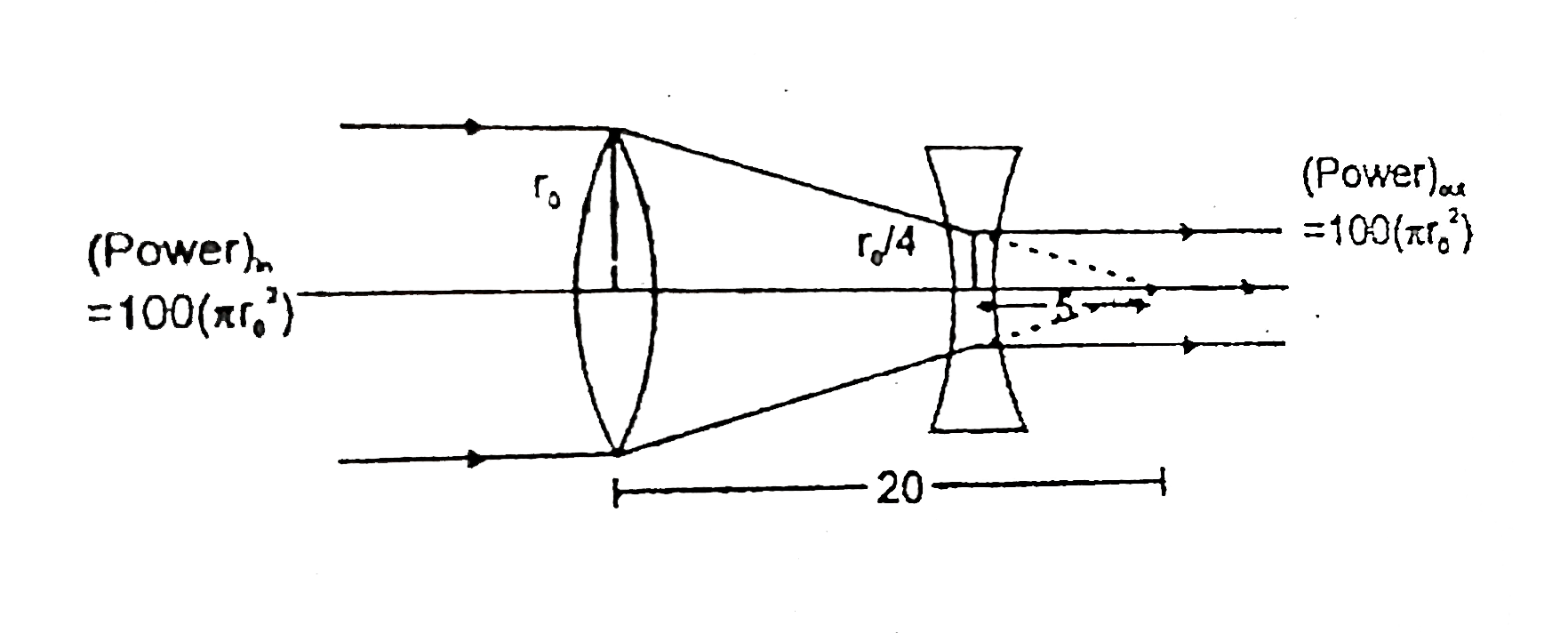
  3. In the figure shown a converging lens and a diverging lens of focal le...

    Text Solution

    |

  4. From the figure shown establish a relation between mu(1),mu(2),mu(3).

    Text Solution

    |

  5. Two point objects are placed on principal axis of a thin converging le...

    Text Solution

    |

  6. A ray R(1) is incident on the plane surface of the glass slab (kept in...

    Text Solution

    |

  7. Assertion: A positively charged rod is held near a neutral conducting ...

    Text Solution

    |

  8. Assertion:A point charge q is placed near an arbitrary shaped solid co...

    Text Solution

    |

  9. Assetrion: If a proton and electron are placed in the same uniform ele...

    Text Solution

    |

  10. Assertion:- In a given situation of arrangement of charges, an extra c...

    Text Solution

    |

  11. STATEMENT 1: The current density vec J at any point in ohmic resistor ...

    Text Solution

    |

  12. Assertion:- To cells of unequal emf E(1) and E(2) having internal resi...

    Text Solution

    |

  13. Statement I : In the circuit in Fig. 7.46, both cells are ideal and of...

    Text Solution

    |

  14. Assertion:- Time constants of the cirucits shown in the figure are sam...

    Text Solution

    |

  15. Assertion:- If dipole (vecP(1)) is moved along the line normal to the ...

    Text Solution

    |

  16. Assertion:- Average power consumed in an accircuit is equal to average...

    Text Solution

    |

  17. Assertion:- Electric field produced by changing magnetic field is nonc...

    Text Solution

    |

  18. Assertion (A) : When tiny circular obstacle is placed in the path of l...

    Text Solution

    |

  19. Assertion:- In standard YDSE set up with visible light, the position o...

    Text Solution

    |

  20. Assertion:- In glass, red light travels faster than blue light. Reas...

    Text Solution

    |