Home
Class 12
PHYSICS
The circuit shown has an idel ammeter wi...

The circuit shown has an idel ammeter with zero resistance and four identical light bulbs which are initially illuminated. A person removes the bulb `R_(4)` from it s socket there by permanently breaking the electrical circuit at that point. Which statement is true about the circuit after removing the bulb?

A

The voltage across BC increases

B

The power supplied by the battery increases

C

The voltage across `R_(1)` increases

D

The bulb `R_(2)` maintains the same brightness.

Text Solution

Verified by Experts

The correct Answer is:
A

Before: `R_(AD)ltR_(2)`
After: `R_(AD)=R_(2)`
So, after breaking cirucit euivalent resistance b/w A and D increases so potential drop across Ad increases, So `V_(BC)` alos increases.
Promotional Banner

Topper's Solved these Questions

  • TEST PAPERS

    ALLEN |Exercise Part-1 Physics|15 Videos
  • TEST PAPERS

    ALLEN |Exercise part-2 physics|73 Videos
  • TEST PAPERS

    ALLEN |Exercise PAPER 2|60 Videos
  • TEST PAPER 4

    ALLEN |Exercise PHYSICS|45 Videos
  • UNIT & DIMENSIONS, BASIC MATHS AND VECTOR

    ALLEN |Exercise Exercise (J-A)|7 Videos

Similar Questions

Explore conceptually related problems

In the diagrams, all light bulbs are identical and all emf sources are ideal and identical. In which circuit (given in option) will each bulb glow with the same brightness as in the circuit shown?

Two identical incandescent light bulbs are connected as shown in figure. When the circuit is connected with an A.C. voltage source of frequency f, which of the following observation will be correct ?

Sonika is working with the circuit shown in the following figure: The circuit has two gaps: X and y. She has wires of five different materials - I, II, III, IV and V. She knows that the bulb will light up only when both gaps are filled with conducting materials. She records her observations in a table. After completing the experiment, ink fell on the paper and she lost entries in row 3. Based on the rest of the information in the table, out of the following what could be the materials in row 3?

An experimental setup of verification of photoelectric effect is shown in the diagram. The voltage across the electrode is measured with the help of an ideal voltmetar, and which can be varied by moving jockey 'J' on the potentiometer wire. The battery used in potentiometer circuit is of 20 V and its internal resistance is 2omega . The resistance of 100 cm long potentiometer wire is 8 omega . The photo current is measured with the help of an ideal ammeter. Two plates of potassium oxide of area 50 cm^(2) at separation 0.5 mm are used in the vacuum tube. Photo current in the circuit is very small so we can treat potentiometer circuit an indepdent circuit. The wavelength of various colours is as follows : |{:("Light",underset("Violet")(1),underset("Blue")(2),underset("Green")(3),underset("Yellow")(4),underset("Orange")(5),underset("Red")(6)),(lambda "in" Årarr,4000-4500,4500-5000,5000-5500,5500-6000,6000-6500,6500-7000):}| When other light falls on the anode plate the ammeter reading remains zero till, jockey till, jockey is moved from the end P to the middle point on the wire PQ. Thereafter the deflection is recorded in the ammeter. The maximum kinetic energy of the emitted electron is :

An experimental setup of verification of photoelectric effect is shown in the diagram. The voltage across the electrode is measured with the help of an ideal voltmetar, and which can be varied by moving jockey 'J' on the potentiometer wire. The battery used in potentiometer circuit is of 20 V and its internal resistance is 2omega . The resistance of 100 cm long potentiometer wire is 8 omega . The photo current is measured with the help of an ideal ammeter. Two plates of potassium oxide of area 50 cm^(2) at separation 0.5 mm are used in the vacuum tube. Photo current in the circuit is very small so we can treat potentiometer circuit an indepdent circuit. The wavelength of various colours is as follows : |{:("Light",underset("Violet")(1),underset("Blue")(2),underset("Green")(3),underset("Yellow")(4),underset("Orange")(5),underset("Red")(6)),(lambda "in" Årarr,4000-4500,4500-5000,5000-5500,5500-6000,6000-6500,6500-7000):}| It is found that ammeter current remians unchanged (2muA) even when the jockey is moved from the 'P' to the middle point of the potentiometer wire. Assuming all the incident photons eject electron and the power of the light incident is 4 xx 10^(-6) W . Then colour of the incident light is :

An experimental setup of verification of photoelectric effect is shown in the diagram. The voltage across the electrode is measured with the help of an ideal voltmetar, and which can be varied by moving jockey 'J' on the potentiometer wire. The battery used in potentiometer circuit is of 20 V and its internal resistance is 2omega . The resistance of 100 cm long potentiometer wire is 8 omega . The photo current is measured with the help of an ideal ammeter. Two plates of potassium oxide of area 50 cm^(2) at separation 0.5 mm are used in the vacuum tube. Photo current in the circuit is very small so we can treat potentiometer circuit an indepdent circuit. The wavelength of various colours is as follows : |{:("Light",underset("Violet")(1),underset("Blue")(2),underset("Green")(3),underset("Yellow")(4),underset("Orange")(5),underset("Red")(6)),(lambda "in" Årarr,4000-4500,4500-5000,5000-5500,5500-6000,6000-6500,6500-7000):}| When radiation falls on the cathode plate a current of 2muA is recorded in the ammeter. Assuming that the vecuum tube setup follows ohm's law, the equivalent resistance of vacuum tube operating in this case when jockey is at end P.

An experimental setup of verification of photoelectric effect is shown in the diagram. The voltage across the electrode is measured with the help of an ideal voltmetar, and which can be varied by moving jockey 'J' on the potentiometer wire. The battery used in potentiometer circuit is of 20 V and its internal resistance is 2omega . The resistance of 100 cm long potentiometer wire is 8 omega . The photo current is measured with the help of an ideal ammeter. Two plates of potassium oxide of area 50 cm^(2) at separation 0.5 mm are used in the vacuum tube. Photo current in the circuit is very small so we can treat potentiometer circuit an indepdent circuit. The wavelength of various colours is as follows : |{:("Light",underset("Violet")(1),underset("Blue")(2),underset("Green")(3),underset("Yellow")(4),underset("Orange")(5),underset("Red")(6)),(lambda "in" Årarr,4000-4500,4500-5000,5000-5500,5500-6000,6000-6500,6500-7000):}| The number of electrons appeared on the surface of the cathode plate, when the jockey is connected at the ened 'P' of the potentiometer wire. Assume that no radiation is falling on the plates.

In the shown expermiental setup to study photoelectric effect, two conducting electrodes are enclosed in an evacuated glass-tube as shown. A parallel beam of monochromatic light, falls on photosensitive electrodes. The emf of battery shwon is high enough such that all photoelectron ejected from left electrode will reach the right electrode. Under initial conditions photoelectrons are emitted. AS changes are made in each situation of column-I, Match the statements in column-I with results in column-II. {:(,"Column I",,"Column II"),((A),"If frequency of incident light is increased keeping its intensity constant",(p),"magnitude of stopping potential"),((B),"If frequency of incident light is increased and its intensity is decreased",(q),"current through circuit may stop"),((C),"If work function of photo sensitive electrode is increased",(r),"maximum kinetic energy of ejected photoelectrons will increase"),((D),"If intensity of incident light is increased keeping its frequency constant",(s),"saturation current will increase"):}

ALLEN -TEST PAPERS-PAPER 3
  1. Variation of x-component of electric field with x-coordinate in a regi...

    Text Solution

    |

  2. Power transfer by a non-ideal cell to an external resistor can be same...

    Text Solution

    |

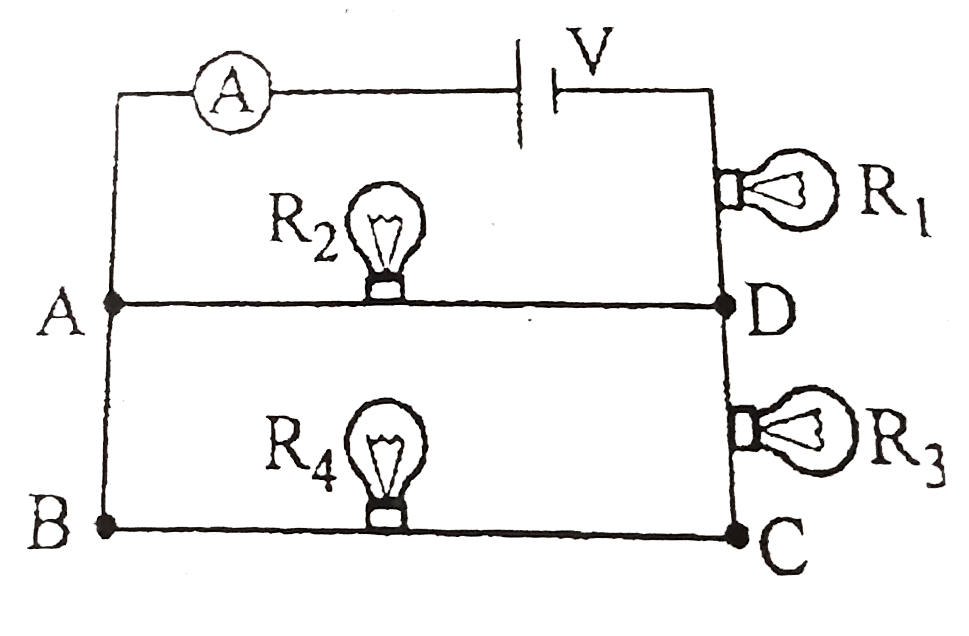
  3. The circuit shown has an idel ammeter with zero resistance and four id...

    Text Solution

    |

  4. Consider a capacitor-charging circuit.Let Q(1) be the charge given to ...

    Text Solution

    |

  5. If magnetic field in space is 1Thati, electric field is 10 N//Chati, n...

    Text Solution

    |

  6. Consider the uniform magnetic field shown: Starting from point P ...

    Text Solution

    |

  7. The figure shows a particle (carrying charge +q) at the orgin. A unifo...

    Text Solution

    |

  8. Which one of the following modifications may increase the senstivity o...

    Text Solution

    |

  9. In the circuit the rms value of voltage across the capacitor C, induct...

    Text Solution

    |

  10. Two bodeis A and B of masses 5.00 kg and 10.0 kg respectively moving i...

    Text Solution

    |

  11. A ball of mass 1 kg strikes a heavy plarform elastically, moving upwar...

    Text Solution

    |

  12. A loop is formed by two parallel conductors connected by a solenoid wi...

    Text Solution

    |

  13. Figure shows the relationship between tensile stress and strain for a ...

    Text Solution

    |

  14. Figure shows the relationship between tensile stress and strain for a ...

    Text Solution

    |

  15. Figure shows the relationship between tensile stress and strain for a ...

    Text Solution

    |

  16. A siphon tube is discharging a liquid of density 900(kg)/(m^(3)) as ...

    Text Solution

    |

  17. A siphon tube is discharging a liquid of density 900(kg)/(m^(3)) as ...

    Text Solution

    |

  18. A rope placed straight on a frictionless floor is pulled longtudinally...

    Text Solution

    |

  19. A steel ball strikes a fixed smooth steel plate placed on a horizontal...

    Text Solution

    |

  20. A ball is thrown vertically upwards. It was observed at a height h twi...

    Text Solution

    |