Home
Class 12
PHYSICS
In the circuit shown in Fig. 4.41, calcu...

In the circuit shown in Fig. 4.41, calculate the current in each resistor and potential difference across each resistor.

Text Solution

Verified by Experts

The correct Answer is:
(B)

Impulse `=` Change in momentum `= 1(4hat(i) + hat(j)) - 1 (6hat(i) + hat(j)) = -2hat(i)`
Which is perpendicular to the wall.
Component of initial velocity along `hat(i) = 6hat(i) rArr` Speed of approach `= 6 m//s`
Similarly speed of separation `= 4 ms^(-1) rArr e = (4)/(6) = (2)/(3)`
Promotional Banner

Topper's Solved these Questions

  • CURRENT ELECTRICITY

    ALLEN |Exercise EXERCISE-III|26 Videos
  • CURRENT ELECTRICITY

    ALLEN |Exercise EXERCISE-IV A|32 Videos
  • CIRCULAR MOTION

    ALLEN |Exercise EXERCISE (J-A)|6 Videos
  • GEOMETRICAL OPTICS

    ALLEN |Exercise subjective|14 Videos

Similar Questions

Explore conceptually related problems

In the given circuit diagram, calculate: the value of current through each resistor

400 J of heat is produced in 4 s in a 4.0ohm resistor. Find the potential difference across the resistor.

In the circuit of adjoining figure the current through 12 Omega resistor will be

In the circuit shown, the current in the 1 Omega resistor is ......

100 J of heat is producec! in each second in a 4 Omega resistance. Find the potential difference across the resistor.

A current of 200 mA flows through a 4 kOhm resistor. What is the potential difference across the resistor?

In the circuit shown in Fig.6.2, the heat produced in 5Omega resistor, due to the current flowing through it is 10 calorie per second. Find the heat produced in 4Omega resistor.

An electric lamp, whose resistance is 20 Omega , and a conductor of 4 Omega resistance are connected to a 6 V battery (see figure). Calculate (a) the total resistance of the circuit, (b) the current through the circuit, and (c ) the potential difference across the electric lamp and conductor.

If power dissipated in the 9 Omega resistor in the resistor shown is 36 W , the potential difference across the 2 Omega resistor is

ALLEN -CURRENT ELECTRICITY-EX.II
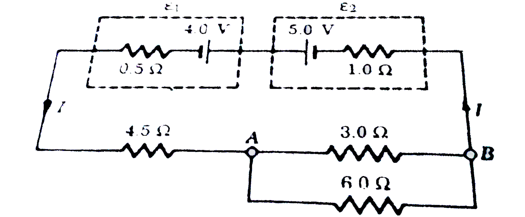
  1. In the circuit shown in Fig. 4.41, calculate the current in each resis...

    Text Solution

    |

  2. In the Bohr's model of hy drogen atom, the electron moves around the n...

    Text Solution

    |

  3. Lengths and cross-sectional areas of three copper wires are (l, A ), (...

    Text Solution

    |

  4. When a piece of aliminium wire of finite length is drawn through a ser...

    Text Solution

    |

  5. Every atom makes one free electron in copper. If 1.1 ampere current is...

    Text Solution

    |

  6. A metal wire of resistance R is cut into three equal pieces that are t...

    Text Solution

    |

  7. Two cells X and Y are connected to a resistance of 10Omega shown in th...

    Text Solution

    |

  8. Masses of 3 wires of same metal are in the ratio 1 : 2 : 3 and their l...

    Text Solution

    |

  9. As the temperature of a metallic resistor is increased,the product of ...

    Text Solution

    |

  10. What will b e the equivalent resistance b etween the A and D?

    Text Solution

    |

  11. In the arrangement of resistances shown in the circuit. The potential...

    Text Solution

    |

  12. It is observed in a potentiometer experiment that no current passes th...

    Text Solution

    |

  13. The resistance across P and Q in the given figure is

    Text Solution

    |

  14. When no current is passed through a conductor,

    Text Solution

    |

  15. A steady current flows in a metallic conductor of non-uniform cross-se...

    Text Solution

    |

  16. Internal resistance of a cell depends on

    Text Solution

    |

  17. The resistance of the circuit between A and B is:-

    Text Solution

    |

  18. The number of free electrons per 100 mm of ordinary copper wire is 2xx...

    Text Solution

    |

  19. The potential difference between the terminals of a cells is found to ...

    Text Solution

    |

  20. What is the reading of ammeter is adjoining circuit diagram.

    Text Solution

    |

  21. The following diagram shows the circuit for the comparision of e.m.f. ...

    Text Solution

    |